
Related Manuals for ASROCK IMB-A182P


Summary of Contents for ASROCK IMB-A182P
- Page 1 IMB-A182 User Manual Version 1.0 Published September 2015 Copyright©2015 ASRock INC. All rights reserved.
- Page 2 (including damages for loss of profits, loss of business, loss of data, interruption of business and the like), even if ASRock has been advised of the possibility of such damages arising from any defect or error in the documentation or product.
-
Page 3: Table Of Contents
Contents 1. Introduction ..............5 1.1 Package Contents ............5 1.2 Specifications ..............6 1.3 Motherboard Layout ............. 8 1.4 I/O Panel ..............10 2. Installation ..............11 2.1 Installing Memory Modules (DIMM) ....... 12 2.2 Expansion Slots (PCI Express Slots) ......13 2.3 Jumpers Setup ............... -
Page 4: Introduction
ASRock’s web- site without further notice. You may find the latest VGA cards and CPU support list on ASRock’s website as well. ASRock website http://www.asrock.com... -
Page 5: Specifications
1.2 Specifications Platform MB Dimension - Mini-ITX Form Factor: 6.7-in x 6.7-in, 17.0 cm x 17.0 cm - All Solid CAP Fanless - Fan or Fanless (Depend on GPU used) System - AMD Steppe Eagle SOC System Memory - 2 x 204pin SO-DIMM - One Channel - Up to DDR3 1600 MHz Display - Embedded ATI Radeon ®... - Page 6 Internal I/O Display - LVDS (2-ch/24bits) + Inverter connector (IMB-A182) - 1 x rear HDMI Display - 2 x rear HDMI (IMB-A182-H) Storage - 1 x SATA3 port - 1 x mSATA - 4 x USB2.0 ports (by two 2x5 K9 2.54mm Headers) Audio - Front Audio Header - 1x4 Spdif Header...
- Page 7 * For detailed product information, please visit our website: http://www.asrock.com...
-
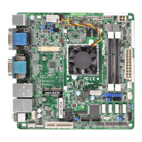
Page 8: Motherboard Layout
1.3 Motherboard Layout... - Page 9 1 : LVDS Power (VDD Power) Jumper 2 : Panel Backlight Power Jumper 3 : COM Port Pin9/Power Setting Jumpers (For COM1, COM3) 4 : Backlight Control Signal Setting Header 5 : Inverter Power/Control Header 6 : Panel Backlight & Audio AMP Volume Control Header 7 : 4-Pin CPU FAN Connector (+12V) 8 : ATX Power Connector (Input 12V) 9 : 20-pin ATX Power Input Connector...
-
Page 10: I/O Panel
1.4 I/O Panel USB 2.0 Ports (USB01) USB 2.0 Ports (USB6_7) Serial Port (COM1) USB 3.0 Ports (USB3_0_1) Serial Port (COM3) 10 HDMI Port (HDMI2) LAN RJ-45 Port (LAN1) 11 HDMI Port (HDMI1) (Optional)* LAN RJ-45 Port (LAN2) 12 D-Sub (VGA1) Front Speaker (Lime) 13 PS/2 Keyboard/Mouse Port Microphone (Pink) -
Page 11: Installation
Chapter 2: Installation This is a Mini-ITX form factor motherboard. Before you install the mother- board, study the configuration of your chassis to ensure that the mother- board fits into it. Pre-installation Precautions Take note of the following precautions before you install motherboard com- ponents or change any motherboard settings. -
Page 12: Installing Memory Modules (Dimm)
2.1 Installing Memory Modules (DIMM) This motherboard provides two 204-pin DDR3 (Double Data Rate 3) SO- DIMM slots. Step 1. Unlock a DIMM slot by pressing the retaining clips outward. Step 2. Align a DIMM on the slot such that the notch on the DIMM matches the break on the slot. -
Page 13: Expansion Slots (Pci Express Slots)
2.2 Expansion Slots (PCI Express Slots) There is 1 PCI Express slot and 1 mini PCI Express slot on this mother- board. mini-PCIE Slot: MINI_PCIE1 is used for mini PCIE cards. PCIE Slot: The x4 lane width PCIE1 (PCIE 2.0 x4 slot) is used for PCI Express expansion cards. -
Page 14: Jumpers Setup
2.3 Jumpers Setup The illustration shows how jumpers are setup. When the jumper cap is placed on the pins, the jumper is “Short”. If no jumper cap is placed on the pins, the jumper is “Open”. The illustration shows a 3-pin jumper whose pin1 and pin2 are “Short”... - Page 15 ATX/AT Mode Jumper 1-2 : AT Mode 2-3 : ATX Mode (3-pin PWR_JP1) (see p.8, No. 16) Digital Input / Output Power 1-2 : +12V Select 2-3 : +5V (3-pin JGPIO_PWR1) (see p.8, No. 20) Backlight Control Signal 1-2 : +3V Level 2-3 : +5V Level Setting Jumper (3-pin BKT_CTL1)
-
Page 16: Onboard Headers And Connectors
2.4 Onboard Headers and Connectors Onboard headers and connectors are NOT jumpers. Do NOT place jumper caps over these headers and connectors. Plac- ing jumper caps over the headers and connectors will cause permanent damage to the motherboard! LVDS Panel Connector Signal Name Signal Name LVDS_PWR... - Page 17 Panel Backlight & Audio Signal Name AMP Volume Control VOL_UP Header VOL_DW BKT_ON/OFF (7-pin BLT_VOL1) BKT_UP (see p.8, No. 6) BKT_DW Serial ATA3 Connector This Serial ATA3 (SATA3) (SATA_1: see p.8, No. 11) connector supports SATA data cables for internal stor- age devices.
- Page 18 LPC Header This connector supports (19-pin LPC1) Trusted Platform Module (see p.8, No. 23) (TPM) system, which can securely store keys, digital certificates, passwords, and data. A TPM system also helps enhance network se- curity, protects digital identi- ties, and ensures platform integrity.
- Page 19 System Panel Header This header accommodates (9-pin PANEL1) several system front panel RESET# (see p.8, No. 17) functions. PWRBTN# HDLED- PLED- PLED+ HDLED+ Connect the power switch, reset switch and system status indica- tor on the chassis to this header according to the pin assignments below.
- Page 20 CPU Fan Connectors Though this motherboard (4-pin CPU_FAN1) provides a 4-Pin CPU fan +12V (see p.8, No. 7) (Quiet Fan) connector, 3-Pin FAN_SPEED FAN_SPEED_CONTROL CPU fans can still work suc- (4-pin CPU_FAN2) cessfully even without fan FAN_SPEED_CONTROL FAN_SPEED (see p.8, No. 13) speed control.
- Page 21 Digital Input / Output PIN Signal Name PIN Signal Name Pin Header SIO_GP24 SIO_GP20 (10-pin JGPIO1) SIO_GP25 SIO_GP21 (see p.8, No. 14) SIO_GP26 SIO_GP22 SIO_GP27 SIO_GP23 JGPIO_PWR Parameter Range GPI/O input Low Voltage Max. 0.8V GPI/O input High Voltage Min. 2.0V GPI/O output Low Voltage Max. 0.4V GPI/O output High Voltage Min. 2.4V Note : Max. load per GPI/O pin : 12mA Current Max.
-
Page 22: Uefi Setup Utility
Chapter 3: UEFI SETUP UTILITY 3.1 Introduction This section explains how to use the UEFI SETUP UTILITY to configure your system. The UEFI chip on the motherboard stores the UEFI SETUP UTILITY. You may run the UEFI SETUP UTILITY when you start up the computer. -
Page 23: Navigation Keys
3.1.2 Navigation Keys Use < > key or < > key to choose among the selections on the menu bar, and use < > key or < > key to move the cursor up or down to select items, then press <Enter> to get into the sub screen. You can also use the mouse to click your required item. -
Page 24: Main Screen
3.2 Main Screen When you enter the UEFI SETUP UTILITY, the Main screen will appear and display the system overview. -
Page 25: Advanced Screen
3.3 Advanced Screen In this section, you may set the configurations for the following items: CPU Configuration, Chipset Configuration, Storage Configuration, Super IO Configuration, ACPI Configuration and USB Configuration. Setting wrong values in this section may cause the system to malfunction. -
Page 26: Cpu Configuration
3.3.1 CPU Configuration Cool ‘n‘ Quiet Use this item to enable or disable AMD’s Cool ‘n’ Quiet technol- ogy. The default value is [Enabled]. Configuration options: [Enabled] ® and [Disabled]. If you install Windows 8.1 / 8 / 7 / Vista and want to enable this function, please set this item to [Enabled]. Please note that enabling this function may reduce CPU voltage and mem- ory frequency, and lead to system stability or compatibility issue with some memory modules or power supplies. -
Page 27: Chipset Configuration
3.3.2 Chipset Configuration DRAM Frequency If [Auto] is selected, the motherboard will detect the memory module(s) inserted and assigns appropriate frequency automati- cally. DRAM Voltage Use this to adjust DRAM voltage. Share Memory Configure the size of memory that is allocated to the integrated graphics processor when the system boots up. - Page 28 Onboard HD Audio Select [Auto], [Enabled] or [Disabled] for the onboard HD Audio fea- ture. Front Panel Select [Auto] or [Disabled] for the onboard HD Audio Front Panel. Onboard LAN 1 This allows you to enable or disable the Onboard LAN 1. Onboard LAN 2 This allows you to enable or disable the Onboard LAN 2.
-
Page 29: Storage Configuration
3.3.3 Storage Configuration SATA Controller Use this item to enable or disable the SATA Controller feature. SATA Mode Selection Use this to select SATA mode. Configuration options: [IDE Mode], [AHCI Mode] and [Disabled]. The default value is [AHCI Mode]. AHCI (Advanced Host Controller Interface) supports NCQ and other new features that will improve SATA disk performance but IDE mode does not have these advantages. -
Page 30: Super Io Configuration
3.3.4 Super IO Configuration COM1 Configuration Use this to set the parameters of COM1. Select COM1 port type: [RS232], [RS422] or [RS485]. COM2 Configuration Use this to set the parameters of COM2. COM3 Configuration Use this to set the parameters of COM3. Select COM3 port type: [RS232], [RS422] or [RS485]. -
Page 31: Acpi Configuration
3.3.5 ACPI Configuration Suspend to RAM Select disable for ACPI suspend type S1. It is recommended to se- lect auto for ACPI S3 power saving. ACPI HPET Table Enable the High Precision Event Timer for better performance. PS/2 Keyboard Power On Use this to enable or disable the PS/2 keyboard to turn on the sys- tem from power-soft-off mode. -
Page 32: Usb Configuration
3.3.6 USB Configuration USB Controller Use this item to enable or disable the use of USB controller. Legacy USB Support Use this option to select legacy support for USB devices. There are four confi guration options: [Enabled], [Auto], [Disabled] and [UEFI Setup Only]. -
Page 33: Tool
3.4 Tool UEFI Update Utility Instant Flash Instant Flash is a UEFI flash utility embedded in Flash ROM. This convenient UEFI update tool allows you to update system UEFI without entering operating systems first like MS-DOS or Win- ® dows . Just save the new UEFI file to your USB flash drive, flop- py disk or hard drive and launch this tool, then you can update your UEFI only in a few clicks without preparing an additional floppy diskette or other complicated flash utility. Please be noted that the USB flash drive or hard drive must use FAT32/16/12 file... -
Page 34: Hardware Health Event Monitoring Screen
3.5 Hardware Health Event Monitoring Screen This section allows you to monitor the status of the hardware on your sys- tem, including the parameters of the CPU temperature, motherboard tem- perature, fan speed and voltage. CPU FAN1 Setting This allows you to set CPU FAN1’s speed. The default value is [Full On]. -
Page 35: Boot Screen
3.6 Boot Screen This section displays the available devices on your system for you to con- figure the boot settings and the boot priority. Boot From Onboard LAN Use this to enable or disable Boot From Onboard LAN. Setup Prompt Timeout This shows the number of seconds to wait for the setup activation key. - Page 36 CSM (Compatibility Support Module) Enable to launch the Compatibility Support Module. If you are using Windows 8.1 / 8 64-bit UEFI and all of your devices support UEFI, you may also disable CSM for faster boot speed. Launch PXE OpROM Policy Select UEFI only to run those that support UEFI option ROM only.
-
Page 37: Security Screen
3.7 Security Screen In this section you may set or change the supervisor/user password for the system. You may also clear the user password. Secure Boot Use this to enable or disable Secure Boot. The default value is [Dis- abled]. -
Page 38: Exit Screen
3.8 Exit Screen Save Changes and Exit When you select this option the following message, “Save configu- ration changes and exit setup?” will pop out. Select [OK] to save changes and exit the UEFI SETUP UTILITY. Discard Changes and Exit When you select this option the following message, “Discard changes and exit setup?”... -
Page 39: Software Support
The Utilities Menu shows the application software that the motherboard sup- ports. Click on a specific item then follow the installation wizard to install it. 4.2.4 Contact Information If you need to contact ASRock or want to know more about ASRock, you’re welcome to visit ASRock’s website at http://www.asrock.com; or you may con- tact your dealer for further information.
Need help?
Do you have a question about the IMB-A182P and is the answer not in the manual?
Questions and answers