Advertisement
Quick Links
Advertisement

Subscribe to Our Youtube Channel
Related Manuals for Little Seeds B346860306COM4


Summary of Contents for Little Seeds B346860306COM4
- Page 1 B346860306COM4 Date of Purchase ___ / ___ / ___ Lot Number:...
- Page 2 Vous trouverez les traductions en français Two adults recommended à la fin de ce manuel. for assembly This product is not intended for commercial use. Do NOT return this product. Follow little seeds on For missing or broken parts - Visit littleseedskids.com - Call 1-800-489-3351...
-
Page 3: Helpful Hints
Do NOT return this product! Contact our friendly customer service team first for help. Assembly Tips Call us! 1-800-489-3351 Monday-Friday 9am - 5pm CST YouTube Visit littleseedskids.com to view the limited warranty valid in the U.S. and Canada. Helpful Hints PEOPLE NEEDED FOR ASSEMBLY: 1-2 ESTIMATED ASSEMBLY TIME: 1 HOUR - Open your item in the area you plan to keep it for less heavy lifting... -
Page 4: Before You Start
Before You Start Read through each step carefully and follow the proper order Separate and count all your parts and hardware Give yourself enough room for the assembly process Have the following tools: Flat Head Screwdriver, #2 Phillips Head Screwdriver and Hammer Caution: If using a power drill or power screwdriver for screwing, please be aware to slow down and stop when screw is tight. -
Page 5: Board Identification
Board Identification Lower Left End Panel Lower Right End Panel Upper Left End Panel Upper Right End Panel 36860306030 36860306040 36860306010 36860306020 Adjustable Shelf Apron Divider 36860306080 36860306060 36860306070 36860306050 Drawer Front Lower Fixed Shelf Upper Fixed Shelf Center Shelf 36860306121 36860306100 36860306090... - Page 6 Board Identification SIDE SIDE BACK Drawer Side Drawer Back Drawer Bottom 39991140346200C 39991140051340B 36860331160 Bottom Shoe Apron Shoe Shelf 36860306170 36860306191 36860306180 Shoe Side Upper Back Panel Lower Back Panel 36860306200 K686030600 K686030610 littleseedskids.com...
- Page 7 Board Identification This piece is paper board construction. It is not made from wood but is required for the assembly of your unit. SIDE BACK SIDE littleseedskids.com...
-
Page 8: Parts List
Parts List Actual Size #A80250 #A22620 #A22610 #A53510 Shelf Support Cam Lock Cam Bolt Angle Bracket #A21660 #A12120 #A21110 #A11080 #A12700 Wood Dowel 7/16" Pan Head Nail 7/16" Flat head 7/8" Pan Head #A13410 #A20940 #A13020 #A21970 #A23030 1-3/4" FLAT HEAD Wall Anchor 1-1/4"... - Page 9 Parts List Not Actual Size Left Left Right Right Cabinet Drawer Drawer Cabinet #A54510 Member Runner Runner Member Drawer Bracket #A56770 Drawer Slide Package #I20630 #A84050 Telescoping Tube Wall Anchor Kit littleseedskids.com...
- Page 10 Step 1 (x6) (x1) #A53510 #A12120 #A84050 Assemble the apron (F) and the top (G) using the angle brackets and wall anchor kit as shown below. (x3) * Raw Edges are Shaded. littleseedskids.com...
- Page 11 Step 2 (x4) (x4) #A22610 #A21660 Insert two wood dowels and two cam bolts into upper left end panel (A) & upper right end panel (B). & littleseedskids.com...
- Page 12 Step 3 Quick Assembly (x4) (x4) A21660 A22620 Proper orientation of CAM LOCK Insert four wood dowels and four cam locks into upper fixed shelf (I). littleseedskids.com...
- Page 13 Step 4 (x3) (x6) (x4) #A53510 #A12120 #A22610 Assemble angle brackets and insert four cam bolts as shown below. (x3) littleseedskids.com...
- Page 14 Step 5 Attach the upper left end panel (A) & upper right end panel (B) to the upper fixed shelf (I) using the cam system. * Raw Edges are Shaded. littleseedskids.com...
- Page 15 Step 6 (x8) #A23030 Attach the top (G) and the center shelf (K) to the upper left end panel (A) & upper right end panel (B) using eight screws. * Raw Edges are Shaded. littleseedskids.com...
- Page 16 Step 7 (x3) (x1) #A56770 #A11080 Attach the right drawer slide to the lower right end panel (D) as shown below. * Raw Edges are Shaded. finished edge littleseedskids.com...
- Page 17 Step 8 (x2) (x6) (x2) #A22620 #A22610 #A21660 Insert six cam bolts, two cam locks, and two wood dowels into the lower right end panel (D). Quick * Raw Edges are Shaded. Assembly Proper orientation of CAM LOCK littleseedskids.com...
- Page 18 Step 9 (x1) (x3) #A56770 #A11080 Attach the left drawer slide to the lower left end panel (C) as shown below. * Raw Edges are Shaded. finished edge littleseedskids.com...
- Page 19 Step 10 (x2) (x6) (x2) #A22620 #A22610 #A21660 Insert six cam bolts, two cam locks, and two wood dowels into the lower left end panel (C). Quick Assembly Proper orientation of CAM LOCK * Raw Edges are Shaded. littleseedskids.com...
- Page 20 Step 11 Quick Assembly (x8) (x8) #A22620 #A21660 Proper orientation of CAM LOCK Insert four wood dowels and four cam locks into lower fixed shelf (J). (x2) littleseedskids.com...
- Page 21 Step 12 (x4) #A21660 Insert two wood dowels into large holes in divider part (E). (x2) littleseedskids.com...
- Page 22 Step 13 (x3) (x4) (x6) (x4) #A53510 #A22620 #A12120 #A21660 Assemble angle brackets and insert cam locks and wood dowels as shown below. Quick Assembly (x3) Proper orientation of CAM LOCK * Raw Edges are Shaded. littleseedskids.com...
- Page 23 Step 14 (x2) #A23030 Attach the bottom (Q) to the divider (E) using two screws. littleseedskids.com...
- Page 24 Step 15 (x2) #A23030 First, attach the lower fixed shelf (J) to the divider (E) using two screws. Then align the dowels to fit the divider (E) and the second lower fixed shelf (J) together. littleseedskids.com...
- Page 25 Step 16 Fit the dowels in divider (E) into the holes In the lower fixed shelf (J). littleseedskids.com...
- Page 26 Step 17 Attach the lower left end panel (C) and the lower right end panel (D) to the assembly from the previous step using the cam lock system as shown. littleseedskids.com...
- Page 27 Step 18 Assemble the upper and lower portion of the unit using the cam lock system as shown. littleseedskids.com...
- Page 28 Step 19 (x31) #A21110 2 people are required for this step. Carefully turn the unit over onto its front side as shown. Assure that the unit is square. Distance from corner to corner must be equal as shown. * Raw Faces are Shaded. Align the upper back panel with the top of the unit.
- Page 29 Step 20 Quick Assembly (x4) (x4) #A21660 #A22620 Proper orientation of CAM LOCK Insert two wood dowels and two cam bolts into shoe shelf (R). littleseedskids.com...
- Page 30 Step 21 (x2) #A22610 Insert two cam bolts into shoe side (T). littleseedskids.com...
- Page 31 Step 22 (x3) #A13410 Attach the shoe apron (S) to the shoe shelf (R) using three screws. (You may need assistance with this step.) littleseedskids.com...
- Page 32 Step 23 NOTE: For this step, the shoe side part (T) can be placed on the left or the right side of the shoe shelf (R). If you place part (T) on the left, the shoe rack will go on the left side of the unit. If you place part (T) on the right, the shoe rack will go on the right side of the unit.
-
Page 33: Left Side
Step 24 (x2) #A22610 If your shoe rack is being assembled If your shoe rack is being assembled on the left side of the unit, on the right side of the unit, place (2) #A22510 cam bolts in the place (2) #A22510 cam bolts in the lower left end panel (C) as shown below. - Page 34 Step 25 The shoe rack is shown on the right side of the unit. However, the same process will be performed if the shoe rack is placed on the left side of the unit. littleseedskids.com...
- Page 35 Step 26 (x4) #A12120 (x2) #A54510 Line up the drawer bracket stem with holes in drawer side as shown. From other side, insert screws into drawer bracket stem and tighten. Note that one drawer side will have the drawer bracket on the left end and the other on the right end.
- Page 36 Step 27 (x4) #A12120 Attach the drawer front using four screws as shown below. Be sure the groove in the drawer sides are centered with the groove in the drawer front. SIDE SIDE littleseedskids.com...
- Page 37 Step 28 (x4) #A21970 Attach the drawer back using four drive fasteners as shown below. BACK SIDE finished surface SIDE littleseedskids.com...
- Page 38 Step 29 (x1 each) (x4) #A56770 #A11080 Attach the drawer slides to the bottom of the drawer sides. SIDE BACK SIDE littleseedskids.com...
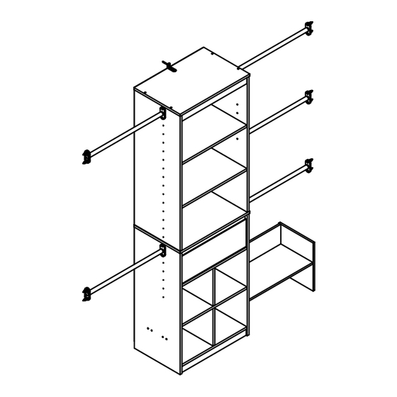
- Page 39 Step 30 (x10) (x10) (x10) #A13020 #A12700 #A20940 (x5) #I20630 First, locate your closet rods where you would like to position them in-line with the holes in the unit and mark hole locations on the wall. Next, If you are using the anchors to fasten the closet rods, insert them into the wall securely by screwing them into the wall using a screwdriver.
- Page 40 Step 31 Notice, the drawer bracket holes are slotted. Drawer fronts can be adjusted by loosening screws, making needed adjustments and retightening screws. cabinet member roller drawer runner roller littleseedskids.com...
- Page 41 Step 32 (x4) #A80250 Place the shelf spoons into the holes in thier desired position and place adjustable shelf (H) in place as shown. littleseedskids.com...
- Page 42 Step 33 (x1) #A84050 IMPORTANT: THIS UNIT MUST BE SECURE TO THE WALL TO HELP PREVENT TIPOVER. FOLLOW THESE INSTRUCTIONS TO INSTALL THE ANTI-TIPPING SAFETY BRACKET PROVIDED WITH THIS PRODUCT. WARNING For Masonry, Concrete, or other wall materials: Consult your local hardware store for appropriate Serious or fatal crushing injuries anchors to securely attach the safety bracket.
- Page 43 MAXIMUM LOADS This unit has been designed to support the maximum loads shown. Exceeding these load limits could cause sagging, instability, product collapse, and/or serious injury. 50 Lbs. each 22.7 kg each 40 Lbs. 18.2 kg 50 Lbs. each 22.7 kg each 40 Lbs.
- Page 44 Visit your local retailer's website, rate your purchased product and leave us some feedback! We would like to extend a big "Thank You" to all of our customers for taking the time to assemble this Little Seeds product, and to give us your valuable feedback. littleseedskids.com...
- Page 45 Español Consejos Útiles (página 3) - Abra su artículo en el área donde usted planea utilizarlo para evitar levantar y moverlo menos - Identificar, ordenar y contar las piezas antes de intentar ensamblar - Las clavijas de compresión se golpean con un martillo - Las diapositivas están marcadas con una R (derecha) y L (izquierda) para la colocación correcta - Asegúrese de que siempre este el punto locaizado en la parte superior de bloqueador de leva este volteadohacia borde exterior...
- Page 46 Español Paso 3 Inserte cuatro espigas de madera y cuatro candados de leva en el soporte fijo superior (I). Paso 4 Monte las escuadras de ángulo e inserte cuatro pernos de leva como se muestra abajo. Paso 5 Conecte el extremo superior izquierdo panel (A) y panel del extremo derecho superior (B) a la estante (I) mediante el sistema de levas fijo superior.
- Page 47 Español Paso 14 Una la parte inferior (Q) con el separador (E) utilizando dos tornillos. Paso 15 Sujete primero el soporte fijo inferior (J) con el separador (E) utilizando dos tornillos. Alinee después las espigas para encajar conjuntamente el separador (E) y el segundo soporte fijo inferior (J).
- Page 48 Español Paso 20 Inserte dos espigas de madera y dos pernos de leva en el soporte de zapatos (R). Paso 21 Inserte dos pernos de leva en el lado de los zapatos (T). Paso 22 Sujete el tablero (S) con el soporte de zapatos (R) utilizando tres tornillos. (Es posible que necesite ayuda para este paso).
- Page 49 Español Paso 27 Sujete el frontal del cajón utilizando cuatro tornillos, tal y como se muestra abajo. Paso 28 Fije la parte posterior del cajón usando cuatro sujetadores de la unidad como se muestra abajo. Paso 29 Fije las correderas del cajón a la parte inferior de los lados del cajón. Paso 30 En primer lugar, ubique las varillas de su clóset en el lugar donde desee colocarlas en línea con los agujeros de unidad y marque puntos de agujeros en la pared.
- Page 50 Español Paso 33 Para mampostería, hormigón u otros materiales de la pared: Consulte a su ferretería local para los anclajes apropiados para fijar firmemente (x1) el soporte de seguridad. #A84050 IMPORTANTE: ESTA UNIDAD DEBE SER ASEGURADA CON LA PARED PARA PREVENIR VOLQUEO. SIGA ESTAS INSTRUCCIONES PARA INSTALAR EL SOPORTE DE SEGURIDAD ANTIVOLQUEO SUMINISTRADO CON ESTE PRODUCTO.
- Page 51 Español Página 43 CARGA MAXIMA Esta unidad ha sido diseñada para soportar la carga máxima anotada. El exceder estos límites puede causar inestabilidad, colapsarse y/o causar serias lesiones. ADVERTENCIA: Riesgo de lesiones a las personas - no coloque un televisor sobre muebles. Este mueble no está...
-
Page 52: Astuces Utiles
Français Astuces Utiles (page 3) -Ouvrez votre article dans la zone que vous prévoyez de le garder pour moins de levage lourd -Identifier, trier et compter les pièces avant d'essayer d'assembler -Les goujons de compression sont taraudés avec un Marteau -Les glissières sont marquées d'un R (droit) et d'un L (gauche) pour un bon placement -Assurez-vous toujours de faire face la pointe situé... - Page 53 Français Étape 4 Assembler des équerres à fixation et insérer quatre serrures à came tel que démontré plus bas. Étape 5 Fixez l’extrémité gauche supérieure panneau (A) & panneau d’extrémité droite supérieure (B) pour la haute tablette (I) en utilisant le système de came fixe. Étape 6 Fixer la partie supérieure (G) et l’étagère centrale (K) à...
- Page 54 Français Étape 14 Attacher le bas (L) à la cloison (E) en utilisant deux vis. Étape 15 Premièrement, attacher la tablette fixée inférieure (J) à la cloison (E) en utilisant deux vis. Puis aligner les goujons pour fixer la cloison (E) et la seconde tablette fixée inférieure (J) ensemble. Étape 16 Fixer les goujons qui sont dans la cloison (E) dans les trous de la tablette fixée inférieure (J).
- Page 55 Français Étape 20 Insérer deux goujons en bois et deux serrures à came dans la tablette à souliers (R). Étape 21 Insérer deux serrures à came dans le côté du soulier (T). Étape 22 Attacher le tablier (S) à la tablette à souliers (R) en utilisant trois vis. (Vous aurez peut-être besoin d'aide pour cette étape.) Étape 23 NOTE : Pour cette étape, la pièce du côté...
- Page 56 Français Étape 28 Fixez le dos du tiroir à l'aide de quatre attaches d'entraînement comme indiqué ci-dessous. Étape 29 Fixez les glissières du tiroir au bas des côtés du tiroir. Étape 30 Premièrement, placer vos barres de garde-robe où vous voulez les positionner, enligner avec les trous dans l'assemblage et marquer l'emplacement des trous sur le mur.
- Page 57 Français Étape 33 Pour la maçonnerie, béton ou d'autres matériaux de mur: Consultez votre magasin local de matériel pour les ancrages (x1) appropriés pour fixer le support de #A84050 sécurité. IMPORTANT: CET APPAREIL DOIT ÊTRE FIXÉ AU MUR POUR AIDER À PRÉVENIR LE BASCULEMENT. SUIVRE CES INSTRUCTIONS POUR INSTALLER LE SUPPORT DE SÉCURITÉ...
- Page 58 Page 43 CHARGES MAXIMALES Ce meuble a été conçu pour supporter les charges maximales indiquées. En excédant ces limites de charge, le meuble pourrait devenir instable, s'effondrer, et/ou causer des blessures graves. AVERTISSEMENT : Risque de blessure corporelle - ne pas placer une télévision sur ce meuble.
Need help?
Do you have a question about the B346860306COM4 and is the answer not in the manual?
Questions and answers