Advertisement
Quick Links
Advertisement

Subscribe to Our Youtube Channel
Related Manuals for Little Seeds B346859103COM2


Summary of Contents for Little Seeds B346859103COM2
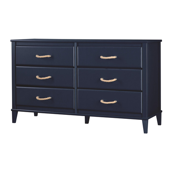
- Page 1 B346859103COM2...
- Page 2 Keep this Assembly Manual for future reference. Two adults recommended for assembly This product is not intended for commercial use. Do NOT return this product. Follow little seeds on For missing or broken parts - Visit littleseedskids.com - Call 1-800-489-3351...
-
Page 3: Helpful Hints
Do NOT return this product! Contact our friendly customer service team first for help. Assembly Tips Call us! 1-800-489-3351 Tube Monday-Friday 9am - 5pm CST Visit littleseedskids.com to view the limited warranty valid in the U.S. and Canada. Helpful Hints PEOPLE NEEDED FOR ASSEMBLY: 2 ESTIMATED ASSEMBLY TIME: 2 HOURS - Open your item in the area you plan to keep it for less heavy lifting... -
Page 4: Before You Start
Before You Start Read through each step carefully and follow the proper order Separate and count all your parts and hardware Give yourself enough room for the assembly process Have the following tools: Flat Head Screwdriver, #2 Phillips Head Screwdriver and Hammer Caution: If using a power drill or power screwdriver for screwing, please be aware to slow down and stop when screw is tight. -
Page 5: Board Identification
Board Identification Left Panel Partition Right Panel 36859103010 36859103030 36859103020 Bottom 36859103040 Stringer 36859103050 36859103060 Front Leg Horizontal Molding Rear Rail Drawer Front 36859103070 36859103080 36859103090 36859103100 littleseedskids.com... - Page 6 Board Identification BACK SIDE Drawer Side Drawer Back Drawer Bottom 39991140346200C 39991140057340B 36859331150 This piece is paper board construction. It is not made from wood but is required for the assembly of your unit. Back Panel K685900000 littleseedskids.com...
- Page 7 Board Identification This piece is paper board construction. It is not made from wood but is required for the assembly of your unit. SIDE BACK SIDE littleseedskids.com...
-
Page 8: Parts List
Parts List Actual Size #A12420 #A21660 #A12120 #A11080 #A22620 #A22610 5/8" pan head wood dowel 7/16" pan head cam lock cam bolt 7/16" flat head #A12950 #A17400 #A21110 #A21970 #A23030 1-1/8" flat head 7/8" screw nail 2" confirmat screw drive fastener #A22910 #A22920 connector bolt... - Page 9 Parts List Not Actual Size left drawer right cabinet right drawer left cabinet runner member member member #A56750 Drawer Slide Package #A84050 #A54510 safety bracket kit drawer brackets #A44390 #A50520 #A50435 rope pull handle littleseedskids.com...
- Page 10 Step 1 #A22910 #A84050 #A22610 Screw six cam bolts and four connector bolts into the top (D) using the holes shown. Attached the safety bracket to the top as shown. Do not tighten this screw. * raw edges are shaded littleseedskids.com...
- Page 11 Step 2 Quick Assembly Proper orientation of CAM LOCK #A21660 #A22620 Insert two cam locks and two wood dowels into both the stringers (F) as shown. littleseedskids.com...
- Page 12 Step 3 #A56750 #A11080 Attach three left cabinet members to the left panel (A) as shown with nine screws. * raw edges are shaded littleseedskids.com...
- Page 13 Step 4 Quick Assembly #A22620 #A21660 #A22610 Proper orientation of CAM LOCK Insert two cam locks and two wood dowels into the left panel (A) as shown. Attached a cam bolt into the hole shown. * raw edges are shaded littleseedskids.com...
- Page 14 Step 5 #A11080 #A56750 Attach three right cabinet members to the right panel (B) as shown with nine screws. * raw edges are shaded littleseedskids.com...
- Page 15 Step 6 Quick Assembly #A22620 #A21660 #A22610 Proper orientation of CAM LOCK Insert two cam locks and two wood dowels into the right panel (B) as shown. Attached a cam bolt into the hole shown. * raw edges are shaded littleseedskids.com...
- Page 16 Step 7 Using four screws, attach the front leg (G) and rear #A12950 rail (H) to the left panel (A) as shown. Please note that the screws will screw into pilot holes in the front leg (G) and rear rail (H). Be sure top edges are flush with each other.
- Page 17 Step 8 #A12950 Using four screws, attach the front leg (G) and rear rail (H) to the right panel (B) as shown. Please note that the screws will screw into pilot holes in the front leg (G) and rear rail (H). Be sure top edges are flush with each other.
- Page 18 Step 9 #A56750 #A11080 #A56750 Attach three right cabinet members to the left surface and three left cabinet members to the right surface of the partition (C) using screws as shown. left surface right surface finished edge littleseedskids.com...
- Page 19 Step 10 Quick Assembly #A22620 #A22610 #A21660 Proper orientation of CAM LOCK Insert two cam locks into the hole on the right surface and a wood dowel into both ends of the partition (A) as shown. Attached a cam bolt to both surfaces as shown. left surface right surface finished edge...
- Page 20 Step 11 #A12420 #A44390 Attach five legs to the bottom surface of the bottom (E) with screws as shown. * raw edges are shaded littleseedskids.com...
- Page 21 Step 12 #A23030 #A22910 Attach for connector bolts to top (E) as shown. Secure the five legs by attaching from the top surface of the bottom (E) with five screws as shown. littleseedskids.com...
- Page 22 Step 13 #A23030 Using two screws, attach the partition (C) to the bottom (E) as shown. finished edge littleseedskids.com...
- Page 23 Step 14 Press the two stringers (F) onto the partition (C) as shown. Turn the cam locks clockwise to lock in place. finished edge finished edge littleseedskids.com...
- Page 24 Step 15 #A23030 Engage the cam bolt in the left panel (A) with the end hole in the stringer (F) while also making sure the wood dowel in the bottom edge of the left panel (A) inserts into the hole in the bottom (E). Turn the cam lock in the stringer (F) clockwise to lock in place. Secure the left Panel (A) to the bottom (E) with two screws as shown.
- Page 25 Step 16 Attach the top (D) to the left panel (A), right panel (B) and partiton (C) as shown. finished edge littleseedskids.com...
- Page 26 Step 17 #A22920 Attach two connectors to each of the four horizontal moldings (I) as shown. You will need to tap the connector with a hammer to fully insert. Be sure the connector is positioned as shown before pushing into holes. littleseedskids.com...
- Page 27 Step 18 With the help of another person, turn your unit over. Press two horizontal moldings (I) onto the top (D) so the connecter engages the connector bolts in the top (D). Turn the screw in the center of the connecter clockwise to lock in place. * raw edges are shaded littleseedskids.com...
- Page 28 Step 19 #A21110 IMPORTANT! THE BACK PANEL IS A STRUCTURAL PART OF THIS UNIT AND MUST BE INSTALLED PROPERLY. Assure that the unit is square. Distance from corner to corner must be equal as shown. Position the back panel as shown on the back edges of the unit making sure the notch in the back panel is positioned at the safety bracket location.
- Page 29 Step 20 With the help of another person, turn your upright as shown. Press two horizontal moldings (I) onto the bottom so the connectors in the horizontal moldings (I) engage the connector bolts in the bottom (E). Turn the screw in the center of the connector clockwise to lock in place.
- Page 30 Step 21 #A54510 #A12120 Attach a drawer bracket to a drawer side with the screws shown. SIDE SIDE littleseedskids.com...
- Page 31 Step 22 #A12120 Note: You will be assembling 6 drawers. They all assemble in the same manner. Attach the drawer sides to the drawer front (J) with screws as shown. Be sure the groove in the drawer sides are centered with the groove in the drawer front. If not, loosen screws in drawer front, adjust and retighten.
- Page 32 Step 23 Slide the drawer bottom (O) into the groove of the drawer sides and drawer front (J) as shown. SIDE finished surface SIDE * raw edges are shaded littleseedskids.com...
- Page 33 Step 24 #A21970 Position the drawer back as shown so the groove in the drawer back captures the edge of the drawer bottom (O). You will need to tap with a hammer to fasten. BACK SIDE SIDE littleseedskids.com...
- Page 34 Step 25 #A56750 #A56750 #A11080 #A17400 #A50435 Attach the left and right drawer runners to the drawer sides. Attach the handle to the drawer front using two screws. SIDE BACK SIDE NOTE: YOU HAVE A CHOICE OF TWO HANDLES / PULLS TO INSTALL ONTO YOUR UNIT. FOR THE ROPE PULL INSTRUCTIONS, SEE NEXT PAGE.
- Page 35 Step 26 #A50520 #A17400 Line up one end of the rope pull with the hole in the drawer front as shown and fasten with screw. Next, bend the rope pull and line up the other end with the hole in the drawer front and attach with other screw.
- Page 36 Step 27 For Masonry, Concrete, or other wall materials: Consult your local hardware store for appropriate anchors to securely attach the safety bracket. #A84050 IMPORTANT: THIS UNIT MUST BE SECURE TO THE WALL TO HELP PREVENT TIPOVER. FOLLOW THESE INSTRUCTIONS TO INSTALL THE ANTI-TIPPING SAFETY BRACKET PROVIDED WITH THIS PRODUCT.
- Page 37 Step 28 Install the drawers as shown. Note: The drawer bracket holes are slotted. Drawer fronts can be adjusted by loosening screws, making needed adjustments and retightening screws. roller cabinet member drawer runner roller littleseedskids.com...
- Page 38 MAXIMUM LOADS This unit has been designed to support the maximum loads shown. Exceeding these load limits could cause sagging, instability, product collapse, and/or serious injury. 75 lbs. 34.1 kg 35 lbs. 15.8 kg (each drawer) Warning: Risk of injury to persons - do not place a television on this furniture. This furniture is not approved for use with a television.
- Page 39 Visit your local retailer's website, rate your purchased product and leave us some feedback! We would like to extend a big "Thank You" to all of our customers for taking the time to assemble this Little Seeds product, and to give us your valuable feedback. littleseedskids.com...
- Page 40 Español Consejos Útiles (página 3) - Abra su artículo en el área donde usted planea utilizarlo para evitar levantar y moverlo menos - Identificar, ordenar y contar las piezas antes de intentar ensamblar - Las clavijas de compresión se golpean con un martillo - Las diapositivas están marcadas con una R (derecha) y L (izquierda) para la colocación correcta - Asegúrese de que siempre este el punto locaizado en la parte superior de bloqueador de leva este volteadohacia borde exterior...
- Page 41 Español Etapa 4 Inserte dos cerraduras de leva y dos clavijas de madera en el panel izquierdo (A) como se muestra. Fije un perno de leva en el agujero que se muestra. Paso 5 Fije tres elementos del gabinete derecho al panel derecho (B) como se muestra con nueve tornillos.
- Page 42 Español Paso 12 Sujetados para los pernos de conexión a la parte superior (E) como se muestra. Asegure las cinco patas sujetándolas desde la superficie superior del fondo (E) con los cinco tornillos, como se muestra. Paso 13 Con dos tornillos fije la división (C) a la parte inferior (E) como se muestra. Paso 14 Presione los dos larguerillos (F) en la división (C) como se muestra.
- Page 43 Español Paso 19 ¡IMPORTANTE! EL PANEL TRASERO ES UNA PARTE ESTRUCTURAL DE ESTA UNIDAD Y DEBE INSTALARSE CORRECTAMENTE. Asegúrese de que la unidad sea cuadrada. La distancia de una esquina a otra esquina debe ser igual a como se muestra. Coloque el panel posterior como se muestra en los bordes traseros de la unidad, asegurándose de que la muesca en el panel posterior se encuentre colocada en la ubicación del soporte de seguridad.
- Page 44 Español Paso 24 Coloque la parte posterior del cajón (L) como se muestra para que la ranura de la parte posterior del cajón (L) capture el borde del fondo del cajón (O). Fijé a los lados del cajón (M&N) con tornillos. Tendrá...
- Page 45 Español OPCION 1: Para asegurar en una viga de la pared (método preferido). Use un detector de vigas, localice la viga en la pared. Coloque la unidad contra la pared y alinee con el soporte de seguridad en esta ubicación. Para hacer este proceso más fácil, se puede perforar un agujero piloto de 1/8"...
-
Page 46: Astuces Utiles
Español Página 39 Registre su producto para recibir lo siguiente: * Detalles de nuevas tendencias - Vistazo a lo nuevo * Encuestas - alec su voz entre su comunidad * Códigos de ofertas y descuentos exclusivos * Fácil y rápido servicio de partes de remplace Para registrar su producto, visite systembuild.com Clasificasión de 5 estrellas Visite el sitio web de su tienda local, califique su comprado... - Page 47 Français Système de Fixation de Came (page 4) Ce Système de Fixation de Came sera utilisé tout au long de l'assemblage Étape 1 Visser six goujons d'assemblage rapide et quatre écrous à manchon à la partie supérieure (D) dans les trous indiqués. Fixer le support de sécurité à la partie supérieure, comme illustré. Étape 2 Insérer deux manchons de serrage et deux chevilles en bois dans les deux longerons (F), comme illustré.
- Page 48 Français Étape 10 Insérer deux manchons de serrage dans le trou sur la surface droite et une cheville en bois dans les deux extrémités de la division (A) comme illustré. Fixer un goujon d'attache rapide aux deux surfaces, comme illustré. Étape 11 Fixer cinq pieds à...
- Page 49 Français Étape 18 Retourner l'unité en vous faisant aider. Enfoncer les deux moulures horizontales (I) dans le sommet (D) pour que le manchon s'engage dans les écrous dans le sommet (D). Tourner la vis au centre du manchon dans le sens horaire pour la bloquer. Étape 19 IMPORTANT ! LE PANNEAU ARRIÈRE EST UN ÉLÉMENT STRUCTUREL DE CETTE UNITÉ...
- Page 50 Français Étape 23 Faire glisser le fond du tiroir (O) dans la rainure des côtés et de la façade (J), comme illustré. Étape 24 Placer l'arrière du tiroir (L) comme illustré afin que la rainure dans la partie arrière (L) prenne le bord du fond du tiroir (O).
- Page 51 Français OPTION 1: Fixation sur un montant mural (méthode préférée) En utilisant un détecteur de montants, locaiiséune planche dans le mur. Placez votre appareil contre le mur, avec le support de sécurité aligné à cet endroit. Pour rendre la conduite de la vis plus facile, vous pouvez percer un trou pilote de 1/8"...
Need help?
Do you have a question about the B346859103COM2 and is the answer not in the manual?
Questions and answers