
Related Manuals for Sanyo VCB3424


Summary of Contents for Sanyo VCB3424
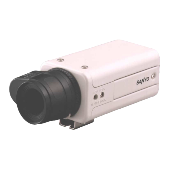
- Page 1 INSTRUCTION MANUAL VCB-3424 B/W CCD Camera About this manual Before installing and using the camera, please read this manual carefully. Be sure to keep it handy for later reference.
- Page 2 OBLIGATIONS In order to obtain warranty service, the product must be delivered to and picked up from an Authorized Sanyo Service Center at the user’s expense, unless specifically stated otherwise in this warranty. The names and addresses of Authorized Sanyo Service Centers may be obtained by writing to SFS Corporation, SFC’s warranty administrator, at any of the addresses listed below, or by calling (toll-free) 1-800-421-5013.
-
Page 3: Table Of Contents
Depending on the conditions of use, installation and environment, FEATURES please be sure to make the appropriate settings and adjustments. If you need help with installation and/or settings, please consult your dealer. • Built-in interline transfer method 1/3" CCD, approx. 270,000 CONTENTS picture elements •... -
Page 4: Information To User
This installation should be made by a qualified service person and Changes or modifications not expressly approved by Sanyo may should conform to all local codes. void the user’s authority to operate this camera. -
Page 5: Precautions
Disconnect the power greasy smoke or steam, where the dampness may get too high, or cord immediately, and consult your dealer (or a Sanyo Authorized where there is a lot of dust. -
Page 6: Parts Names
PARTS NAMES Video output connector (VIDEO OUT: BNC type) Connect this connector to a device such as a VCR or monitor with a VIDEO IN connector. Line phase adjustment volume (LINE PHASE) When using two cameras or more, the image on the monitor may roll vertically when switching sources. This rolling can be minimized by turning this volume. - Page 7 PARTS NAMES Lens mount cap The cap is installed to protect the lens mount section. Remove the lens mount cap before installing a lens (sold separately). Flange-back adjustment screw (FLANGE BACK ADJ.) Flange-back lock screw (FLANGE BACK LOCK) Camera installation bracket The bracket can be fixed at the top or bottom of the camera.
- Page 8 ALC and LEVEL volume level controls are available on the lens for iris adjustments. (Set the A.I. LENS switch to the VIDEO position.) Compatible auto-iris lenses 1/3 inch Sanyo DC type lens VIDEO type lens VCL-CS8LY: Standard angle, f= 8 mm...
-
Page 9: Mounting The Lens
MOUNTING THE LENS Please use a DC type auto-iris lens (sold separately). Checking the lens mount Do not use a lens if length “L” is more than 7 mm. If not, that may damage the camera and prevent proper installation. Remove the lens mount cap from the camera. - Page 10 MOUNTING THE LENS Rewiring the lens cable in the lens iris plug Prepare the lens cable. Cut the cable at the plug, then remove approx. 8 mm of the cable sheath and strip about 2 mm from each wire. Install the lens iris plug. Solder the cable to the pins following the correct pin layout (refer to the table and illustrations), then close the plug cover.
-
Page 11: Connections
CONNECTIONS Basic connection for monitoring or recording The peripheral devices (VCR, monitor, lens, etc.) and cables are sold separately. Make the video signal connection between the camera and the monitor or time lapse VCR. Connect to 24 V AC UL listed class 2 power supply. 24 V 24 V CAUTION:... -
Page 12: Settings
SETTINGS Camera setup section Electronic iris function setting Use a manual or fixed iris lens and set the lens aperture to the shortest F stop. Set the EI VR401 switch to ON position. Note: VIDEO Please refer to the specifications for dynamic A. - Page 13 SETTINGS Lens iris adjustment Backlight compensation setting If using a DC type auto-iris lens, you will need to set the LEVEL Use an auto-iris lens and set the BLC switch to the ON position, to (VR401) volume when shooting in the conditions described below. engage the backlight compensation function.
-
Page 14: Troubleshooting
If it still does not perform When using a camera switcher to connect 2 cameras or more to one correctly, please consult your dealer or a Sanyo Authorized Service monitor, there may be a vertical roll of the images when switched. In Centre. -
Page 15: Specifications
However, in the event of a condensation) problem, the owner is advised not to attempt to make repairs or open Power supply : 24 V AC, 60 Hz the cabinet. Servicing should always be referred to your dealer or Sanyo Authorized Service Centre. English... - Page 16 This file has been downloaded from: www.UsersManualGuide.com User Manual and User Guide for many equipments like mobile phones, photo cameras, monther board, monitors, software, tv, dvd, and othes.. Manual users, user manuals, user guide manual, owners manual, instruction manual, manual owner, manual owner's, manual guide, manual operation, operating manual, user's manual, operating instructions, manual operators, manual operator, manual product, documentation manual, user maintenance, brochure, user reference, pdf manual...
Need help?
Do you have a question about the VCB3424 and is the answer not in the manual?
Questions and answers