Table of Contents
Advertisement
800.998.MATE
t e l
5 1 0 . 8 4 5 . 6 2 8 3
Part Number 2500-0157 Rev D March 2005 Printed in USA
Copyright 2005 Axon Instruments / Molecular Devices Corp.
No part of this manual may be reproduced, stored in a retrieval system, or
transmitted, in any form or by any means, electronic, mechanical, photocopying,
microfilming, recording, or otherwise, without written permission from Molecular
Devices Corp.
QUESTIONS? See Axon's Knowledge Base: http://support.
|
www.autom8.com
|
f a x
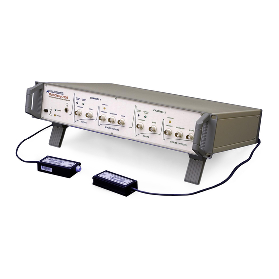
MultiClamp 700B
COMPUTER-CONTROLLED
MICROELECTRODE AMPLIFIER
Theory and Operation
|
6 5 0 Un i ver si t y Ave # 5 , Ber k el ey, CA 9 4 710
|
e - m a i l
5 1 0 . 6 6 5 . 3 9 7 5
axon
i n f o @ a u t o m 8 . c o m
.com
USA
Advertisement
Table of Contents


Need help?
Do you have a question about the AutoMate Scientific MultiClamp 700B and is the answer not in the manual?
Questions and answers