Table of Contents
Advertisement
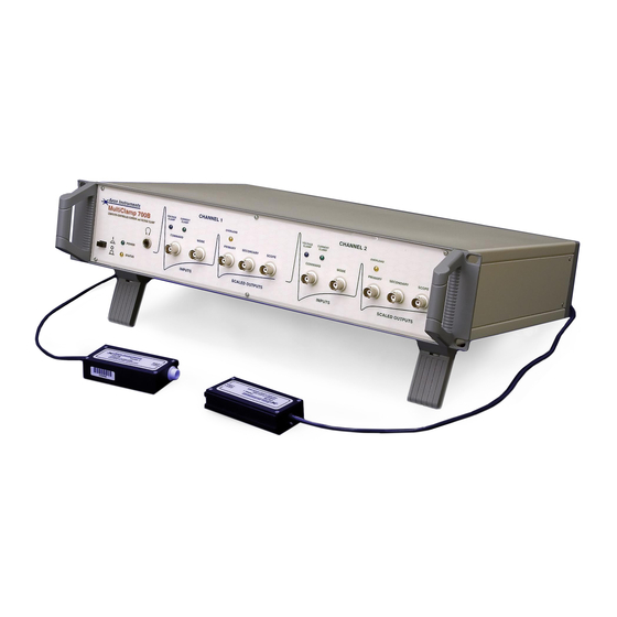
MultiClamp 700B
COMPUTER-CONTROLLED
MICROELECTRODE AMPLIFIER
Theory and Operation
Part Number 2500-0157 Rev D March 2005 Printed in USA
Copyright 2005 Axon Instruments / Molecular Devices Corp.
No part of this manual may be reproduced, stored in a retrieval system, or
transmitted, in any form or by any means, electronic, mechanical, photocopying,
microfilming, recording, or otherwise, without written permission from Molecular
Devices Corp.
QUESTIONS? See Axon's Knowledge Base: http://support.
axon
.com
Advertisement
Table of Contents

Related Manuals for Axon MultiClamp 700B


Summary of Contents for Axon MultiClamp 700B
- Page 1 Theory and Operation Part Number 2500-0157 Rev D March 2005 Printed in USA Copyright 2005 Axon Instruments / Molecular Devices Corp. No part of this manual may be reproduced, stored in a retrieval system, or transmitted, in any form or by any means, electronic, mechanical, photocopying, microfilming, recording, or otherwise, without written permission from Molecular Devices Corp.
- Page 3 !!!!! SAFETY LEASE READ There are important safety issues that you must take into account when using this instrument. Please carefully read the safety warnings starting on page 159 before you use this instrument. VERIFICATION This instrument is extensively tested and thoroughly calibrated before leaving the factory.
-
Page 5: Table Of Contents
Installing the MultiClamp 700B Commander ........... 4 Functional Checkout ..................... 6 Communication with the MultiClamp 700B ............. 6 Setting Parameters in the MultiClamp 700B Commander ........ 7 Toolbar Buttons in the MultiClamp 700B Commander ........9 Test the Noise....................10 Calibration....................... - Page 6 Bridge Balance ....................75 Bridge Balance in the Bath................76 Bridge Balance in the Cell................77 Buzz........................78 Capacitance Compensation ................. 78 Electrode Capacitance Compensation ............. 79 Whole-Cell Capacitance Compensation............80 MultiClamp 700B Theory and Operation, Copyright 2005 Axon Instruments / Molecular Devices...
- Page 7 Table of Contents • v Auto Button..................... 83 Manual Adjustment of Capacitance Compensation ........83 Filtering the Command Stimulus ..............84 Capacitance Neutralization ................. 84 Input Capacitance.................... 84 Adjusting Capacitance Neutralization............. 86 Limitations of Capacitance Neutralization............86 Clear ........................87 Electrochemistry....................
- Page 8 Changing the Fuse ..................121 Glitches......................121 Select Device..................... 122 Series Resistance Compensation ............... 122 Introduction to R Compensation ..............122 Is R Compensation Necessary? ..............124 Adjusting R Compensation ................125 MultiClamp 700B Theory and Operation, Copyright 2005 Axon Instruments / Molecular Devices...
- Page 9 Table of Contents • vii Theory of R Compensation ................129 The ‘Prediction’ Control ................130 The ‘Prediction’ Control ................131 Saturation Effects ..................132 Readjustment of Whole Cell Compensation with ‘Prediction’ ..... 133 The ‘Correction’ Control................134 Readjustment of Whole Cell Compensation with ‘Correction’ ....135 Setting ‘Prediction’...
-
Page 11: Chapter 1 Introduction
Also, an optional CV-7 headstage will allow bilayer recording. The MultiClamp 700B is essentially an analog input / output instrument, similar to conventional amplifiers by Axon Instruments. Thus, BNC-type input and output connections are necessary to communicate with a digitizing interface, oscilloscope or other recording device. - Page 12 We will be pleased to answer any questions regarding the theory and use of the MultiClamp 700B. Any comments and suggestions on the use and design of the MultiClamp 700B will be much appreciated. We welcome reprints of papers describing work performed with the MultiClamp 700B.
-
Page 13: Chapter 2 Installation And Basic Operation
Retain packing materials in case the instrument needs to be returned to the factory at a later date. For the initial checkout, the MultiClamp 700B should be situated on a bench top away from other equipment. Do not install it in a rack until the checkout is complete. -
Page 14: Installing Hardware
1. Connect the appropriate end of the USB cable to the USB connector on the MultiClamp 700B rear panel, and the other end to a free USB port on your 2. Connect the CV-7 headstage(s) to HEADSTAGE #1 and HEADSTAGE #2 rear panel connectors, respectively. - Page 15 Figure 2.1 If the program is unable to find a valid Serial Number, check that the MultiClamp 700B is switched on and that the USB cable is connected properly. 4. If you are using the optional SoftPanel device, click on the SoftPanel tab and click the Scan button.
-
Page 16: Functional Checkout
Communication with the MultiClamp 700B 1. Check that the STATUS light on the front of the MultiClamp 700B is flashing. This indicates that the MultiClamp 700B Commander is polling the MultiClamp 700B, updating its meter displays. -
Page 17: Setting Parameters In The Multiclamp 700B Commander
Installation and Basic Operation • 7 Setting Parameters in the MultiClamp 700B Commander Many parameter fields in the MultiClamp 700B Commander can be set in three different ways. To demonstrate this, press the V-Clamp 1 tab and try the following. - Page 18 For example, right-click the mouse while over the Holding glider, and you will see the following menu. Figure 2.6 MultiClamp 700B Theory and Operation, Copyright 2005 Axon Instruments / Molecular Devices...
-
Page 19: Toolbar Buttons In The Multiclamp 700B Commander
Installation and Basic Operation • 9 Toolbar Buttons in the MultiClamp 700B Commander At the top of the MultiClamp 700B Commander main window is a row of toolbar buttons that provide access to a number of special features. Figure 2.7 Positioning the mouse cursor over each button will, after a short delay, display a Tool Tip for the button. -
Page 20: Test The Noise
Test the Noise All electronic equipment generates some amount of thermal noise. Follow these steps to measure the intrinsic MultiClamp 700B current noise (“Irms”, or the root- mean-square of the current noise): 1. Leave the CV-7 headstage in an “open circuit” configuration (i.e., nothing should be attached to the input of the CV-7). -
Page 21: Calibration
6. If your MultiClamp has more than one CV-7 headstage, repeat steps 1-5 for the second headstage. Calibration The steps below provide a quick check of the calibration of the MultiClamp 700B. It is assumed that appropriate shielding (as described in “Test the Noise”, above) will be used during these tests. - Page 22 3. Plug the CELL connector of the PATCH-1U model cell into the CV-7 headstage. 4. Press the Auto Whole Cell button. 5. Press Auto Cp Fast button. 6. The step response should be ~25 mV MultiClamp 700B Theory and Operation, Copyright 2005 Axon Instruments / Molecular Devices...
-
Page 23: Getting Help In The Multiclamp 700B Commander
700B Commander, because this information is better provided in an interactive way using the On-line Help. Rather, the purpose of this manual is to provide tutorials and detailed information about the design and operation of the MultiClamp 700B amplifier as a whole. Therefore, the On-line Help and this manual complement each other. -
Page 25: Chapter 3 Tutorials
The purpose of this chapter is to lead the user through the basics of patch clamping and ‘sharp’ microelectrode recording, using the PATCH-1U model cell that comes with the MultiClamp 700B. The tutorials are designed to illustrate the operation of the MultiClamp 700B and associated Commander control software. Although this... -
Page 26: Model Cell
Approximately 5 pF stray capacitance to ground. CELL: 10 MΩ "pipette" resistor. 500 MΩ "cell membrane" resistor in parallel with 33 pF cell membrane capacitor. Approximately 5 pF stray capacitance to ground. MultiClamp 700B Theory and Operation, Copyright 2005 Axon Instruments / Molecular Devices... -
Page 27: Tutorial 1 - Electrode In The Bath: Voltage Clamp
Tutorials • 17 Tutorial 1 – Electrode in the Bath: Voltage Clamp 1. Switch on the MultiClamp 700B and run the MultiClamp 700B Commander by double-clicking on the shortcut icon on the desktop of the PC. Press the Reset to Program Defaults toolbar button, or press the F6 key. - Page 28 SYNC output on the rear of the MultiClamp 700B to the External Trigger input on the oscilloscope. See Options / General tab.) The amplitude of the Seal Test pulse is 10 mV.
-
Page 29: Tutorial 2 - Electrode In The Bath: Current Clamp
Note that the model cell used in this tutorial is designed to simulate a patch pipette, rather than a typical intracellular electrode, which generally has a higher resistance. However, the principles illustrated are the same. 1. Set up the MultiClamp 700B and the MultiClamp 700B Commander as in Steps 1-3 of Tutorial 1. Chapter 3... - Page 30 R = V/I = 10 mV/1 nA = 10 MΩ. Alternatively, the resistance can be directly displayed by checking the Resistance checkbox under the Channel 1 meters. MultiClamp 700B Theory and Operation, Copyright 2005 Axon Instruments / Molecular Devices...
-
Page 31: Tutorial 3 - Giga Seal Configuration
Tutorial 3 – Giga Seal Configuration 1. Set up the MultiClamp 700B and the MultiClamp 700B Commander as in Steps 1-3 of Tutorial 1, except that the PATCH connector on the model cell should be plugged into the headstage of the MultiClamp 700B. This connects a 10 GΩ... - Page 32 Note that with a filter setting of 2 kHz the peak-to-peak noise on Primary Output is about 0.5 pA, which is adequate for most single-channel recording. (See Chapter 4 for practical hints on how to reduce the noise further.) MultiClamp 700B Theory and Operation, Copyright 2005 Axon Instruments / Molecular Devices...
- Page 33 Tutorials • 23 6. This section of the MultiClamp 700B Commander displays three other adjustable parameters: Output Gain, AC and Scope. • Use the glider to adjust Output Gain. Note the changes in the scaling factor at Primary Output: Membrane Current, as well as the change in signal amplitude on the oscilloscope.
- Page 34 Test frequency to 200 Hz. Check the Seal Test checkbox; a train of ~1 Volt transients will appear on the Primary Output trace. (These are more easily seen if the oscilloscope is triggered using the SYNC output of the MultiClamp 700B, as described in Tutorial 1.) Figure 3.12...
- Page 35 Tutorials • 25 8. Place the mouse cursor over the button (dual control) opposite Cp Fast. The cursor changes to crossed arrows. (See the figure below.) While holding down the Shift key (to magnify the movement; see Chapter 2) use the glider, sliding the mouse horizontally and vertically, to change the values of the time constant and capacitance, respectively.
-
Page 36: Tutorial 4 - Whole-Cell Configuration: Voltage Clamp
11. Now that the capacitance transients are compensated, it will be possible to increase the amplitude of the Seal Test pulse without overloading the MultiClamp 700B. Set the Seal Test amplitude to 100 mV by placing the cursor over the display (10 mV), double clicking and typing 100 <Enter>. - Page 37 2. Check the Seal Test checkbox; a train of ~0.5 Volt transients decaying over ~2 ms will appear on the Primary Output trace. (These are more easily seen if the oscilloscope is triggered using the SYNC output of the MultiClamp 700B.) Figure 3.15...
- Page 38 The residual step, due to current flow through the “input resistance” of the model cell, can be canceled using the Leak Subtraction feature of the MultiClamp 700B. This subtracts from Primary Output a current that is scaled linearly from the voltage command. (See Chapter 5, LEAK...
- Page 39 Tutorials • 29 SUBTRACTION). Check the Leak Subtraction checkbox and press the button (or use the glider to obtain a flat trace). Figure 3.18 The optimum value is about 500 MΩ, the “input resistance” of the model cell. Manual adjustments of Whole Cell and Cp Fast may be necessary to perfectly compensate the response.
- Page 40 Chapter 5. SERIES RESISTANCE COMPENSATION 9. The MultiClamp 700B is designed to be used with an external pulse generator or computer to provide voltage-clamp (and current-clamp) command steps. However, the Pulse button in the MultiClamp 700B Commander allows you to apply simple, on-off steps with a selectable amplitude and duration.
-
Page 41: Tutorial 5 - Whole-Cell Configuration: Current Clamp
4. Check the box next to “Holding”and, using glider control, vary the holding current (pA) while viewing the Primary Output signal on the oscilloscope and on the MultiClamp 700B Commander voltage meter. The model membrane potential varies smoothly with Holding current. - Page 42 10 MΩ, but in the CELL position you may record slightly higher values (near 14 MΩ) because the electrode resistance is mixed with the cell capacitance and resistance components. MultiClamp 700B Theory and Operation, Copyright 2005 Axon Instruments / Molecular Devices...
- Page 43 Tutorials • 33 To the left of Bridge Balance is the Output Zero button. This works exactly like the corresponding button in voltage clamp, removing constant DC offsets. 7. In current-clamp mode the stray electrode capacitance can cause additional errors, acting to filter the membrane potential signal. This error can be reduced by using electronic compensation of the pipette capacitance.
- Page 44 • The Pipette Capacitance Neutralization feature will be disabled (box will become unchecked). • You will hear an audible tone. MultiClamp 700B Theory and Operation, Copyright 2005 Axon Instruments / Molecular Devices...
- Page 45 Tutorials • 35 • A warning message will appear to indicate the detection of oscillations and the disabling of Pipette Capacitance Neutralization. Figure 3.28 10. You can choose to prevent the warning message from appearing. Go to the Options / Auto menu, and disable (uncheck) the “Display warning” feature. Figure 3.29 Also in the Options / Auto menu, you can alternatively choose to reduce instead of disable Pipette Capacitance Neutralization in IC mode.
- Page 46 Figure 3.31 The time required to reach the selected voltage depends upon the feedback resistor and headstage load. See the MultiClamp 700B Commander on-line Help for more detail. MultiClamp 700B Theory and Operation, Copyright 2005 Axon Instruments / Molecular Devices...
-
Page 47: Tutorial 6 - Whole-Cell Configuration: Automatic Mode Switching
Tutorial 6 – Whole-Cell Configuration: Automatic Mode Switching 1. Set up MultiClamp 700B as follows: Reset to Program Defaults, connect CELL position of Patch-1U model cell (shielded and grounded) to CV-7 headstage. 2. Make the following changes in VC mode: a. - Page 48 = 20 mV. Next, click the radio button for Return to current clamp: After:, and set this value to 500 ms. Close the Options menu to return to the main IC window. Figure 3.34 MultiClamp 700B Theory and Operation, Copyright 2005 Axon Instruments / Molecular Devices...
- Page 49 Tutorials • 39 5. Monitor Primary Output on external oscilloscope. Set display for at least 2 full seconds per sweep. You should observe a slowly charging and discharging voltage response to the Tune current step. Figure 3.35 6. Now check the Auto checkbox next to the Mode buttons. Note that the VC, I=0 and IC buttons are now greyed out, since they are under automatic control.
- Page 50 40 • Tutorials b. MultiClamp 700B will remain in VC for 500 ms, then switch back to IC. A transient due to this mode change will appear, then the potential will begin to decay. c. When the potential again reaches 20 mV (going from positive to negative direction), the MultiClamp 700B will again switch from IC to VC.
- Page 51 Tutorials • 41 careful to turn OFF this external command during the Auto Mode switch. If you do not, then the incoming command will conflict with the Auto Mode switch settings. To disable the external commands, go to the Options / Gains tab, and click the OFF radio button in the VC and IC External Command Sensitivity sections.
-
Page 53: Chapter 4 Guide To Electrophysiological Recording
Guide to Electrophysiological Recording • 43 Chapter 4 Guide to Electrophysiological Recording The purpose of this chapter is to provide practical advice on patch clamping and sharp microelectrode recording, both of which are possible using the MultiClamp 700B. It includes both tutorial-style guidance and technical details for reference. This information has been distilled from textbooks on the subject (see References at the end of this manual) and from experienced researchers working in laboratories around the world. -
Page 54: General Advice
Tissue slices are MultiClamp 700B Theory and Operation, Copyright 2005 Axon Instruments / Molecular Devices... -
Page 55: Optics
This is easily done by blowing out the patch and pressing the I=0 button on The MultiClamp 700B Commander. This will display on the meter the pipette voltage required for zero current through the electrode. If, for instance, the... -
Page 56: Interfacing A Computer
Note: If you use both headstages on the MultiClamp 700B (e.g. for making simultaneous recordings from pairs of cells) you may wonder whether one or both headstage ground sockets need to be connected to the bath electrode. -
Page 57: Computer Noise
Digital computers can generate considerable electrical noise, both via the power ground and via radiative interference from the monitor. For optimal noise performance of the MultiClamp 700B, careful attention should be paid to the placement of the computer. For example, the monitor should not be placed immediately above or below the MultiClamp 700B in the instrument rack. - Page 58 Further details are given under “Low Noise Techniques”, below. MultiClamp 700B Theory and Operation, Copyright 2005 Axon Instruments / Molecular Devices...
-
Page 59: Forming A Gigaseal
Guide to Electrophysiological Recording • 49 Forming a Gigaseal Start with the MultiClamp 700B in voltage clamp mode (VC). Fill a patch pipette with internal solution and secure it firmly in the pipette holder (fill the patch pipette with external solution if cell-attached recording is the goal). Be sure to support the headstage with your other hand so that the micromanipulator will not have to absorb your force. - Page 60 At the same time, steadily increase the holding potential towards –60 or –70 mV; doing this usually helps seal formation. There should be a rapid increase in the resistance. Release the suction when the resistance MultiClamp 700B Theory and Operation, Copyright 2005 Axon Instruments / Molecular Devices...
-
Page 61: Whole-Cell Voltage Clamp Recording
(See Chapter 3, .) This is done TUTORIAL 3 under the Options button at the top of the MultiClamp 700B Commander. After changing the feedback resistor you may need to readjust the Cp Fast and Cp Slow settings. - Page 62 The MultiClamp 700B contains a Zap circuit to aid in breaking into the cell. This circuit delivers a pulse of 1 V DC to the patch for variable durations ranging from 0.1 to 10 ms.
- Page 63 Figure 4.2. Going whole-cell: capacity transients observed when rupturing the patch. After achieving stable whole-cell access, press the Auto button in the Whole Cell section of the MultiClamp 700B Commander to compensate the whole-cell capacitance transient. It may be necessary to manually adjust the Whole Cell pF and MΩ...
-
Page 64: Perforated-Patch Recording
SERIES RESISTANCE COMPENSATION The Leak Subtraction feature of the MultiClamp 700B allows you to subtract linear leak currents from the membrane current traces. Generally speaking it is not a good idea to do this in the whole-cell configuration, because whole cells may contain background currents that have some dependence on voltage. -
Page 65: Low Noise Techniques
Figure 4.3. Going whole-cell: capacity transients observed during amphotericin partitioning. Low Noise Techniques The MultiClamp 700B is capable of producing stable, low-noise recordings. To realize this performance the user must pay close attention to other sources of noise. This is because the total rms noise of a patch clamp recording is the square root of the sum of the individual squared rms noise sources. - Page 66 90° is the "loss factor". The loss factor is related to the power dissipated in the dielectric. Since energy is lost in the dielectric, dielectrics ( e.g. , glasses) are commonly referred to as "lossy". MultiClamp 700B Theory and Operation, Copyright 2005 Axon Instruments / Molecular Devices...
- Page 67 Guide to Electrophysiological Recording • 57 softening temperature. High lead glasses are easier to pull, but have been reported to modify channel currents (e.g. see Cota and Armstrong, Furman and Tanaka, Biophysical J. 53:107-109, 1988; Furman and Tanaka, Biophysical J. 53:287-292, 1988).
- Page 68 Any solution that gets near the back of the pipette should be dried with dry air or nitrogen to keep it from getting into the holder. Holders that become contaminated with solution should be MultiClamp 700B Theory and Operation, Copyright 2005 Axon Instruments / Molecular Devices...
-
Page 69: Sharp Microelectrode Recording
The CV-7 headstage of the MultiClamp 700B contains both an Axopatch-like current-to-voltage converter and an Axoclamp-like voltage follower circuit. The former is activated when VC (V-Clamp) mode is selected in the MultiClamp 700B Commander, the latter when I=0 or IC (I-Clamp) mode is selected. Although the... -
Page 70: Sharp Microelectrode Or Patch Electrode
Microelectrode Properties Users of sharp microelectrodes spend far more time than patch clampers worrying about the properties of their electrodes. This is because the higher resistance of MultiClamp 700B Theory and Operation, Copyright 2005 Axon Instruments / Molecular Devices... - Page 71 Guide to Electrophysiological Recording • 61 sharp microelectrodes may introduce a number of undesirable properties. For best results, the microelectrode voltage must settle rapidly after a current pulse, and the microelectrode must be able to pass current without large changes in resistance. The important factors that need to be considered are discussed below.
- Page 72 Another method is to coat the microelectrode with Sylgard #184 or Q-dope (model airplane glue). The selected material should be painted onto the electrode to within 100 µm of the tip. MultiClamp 700B Theory and Operation, Copyright 2005 Axon Instruments / Molecular Devices...
- Page 73 In IC mode, pass a constant current into the bath for about 10 seconds; this can be done by setting a Holding current in the MultiClamp 700B Commander and checking the Holding checkbox. The current magnitude should be the same as the maximum sustained current likely to be passed during the experiment.
-
Page 74: Filling Solutions
Impaling Cells Start with the MultiClamp 700B in IC mode (I-Clamp). Fill a microelectrode with internal solution and secure it firmly in the pipette holder. Be sure to support the headstage with your other hand so that the micromanipulator will not have to absorb your force. - Page 75 Check the Tuning checkbox and observe the Primary Output: Membrane Potential on a scope. Move the electrode tip close to where cells are likely to be encountered, and then increase Pipette Capacitance Neutralization in the MultiClamp 700B Commander to give the fastest step response. It is advisable to adjust the...
-
Page 77: Chapter 5 Reference Section
It is expected that the MultiClamp 700B Commander On-line Help will answer many questions about the operation of the MultiClamp 700B. This chapter provides details of the theory and operation of the MultiClamp 700B, beyond what is available in the On-line Help. The information in this section is gathered under a number of broad topics, arranged in alphabetical order. -
Page 78: Audio Monitor
DC signal, e.g. the membrane potential. The default setting for the VCO is 2200 Hz at 0 V ranging to 300 Hz at -100 mV. MultiClamp 700B Theory and Operation, Copyright 2005 Axon Instruments / Molecular Devices... - Page 79 Reference Section • 69 Audio output can be monitored by making connections to the MultiClamp 700B in one of three different ways: 1. Connect the rear panel AUDIO OUTPUT to the Line IN connector of your computer sound card. This allows the MultiClamp 700B to use the computer’s speaker.
- Page 80 2. Connect headphones or remote powered speakers to the front panel PHONES output or the rear panel AUDIO OUTPUT. This allows dedicated use of the headphones or external speakers by the MultiClamp 700B. Figure 5.2. Possible Audio configuration #2. MultiClamp 700B Theory and Operation, Copyright 2005 Axon Instruments / Molecular Devices...
- Page 81 Figure 5.3. Possible Audio configuration #3. WARNING : Never connect the computer’s microphone jack to Audio connectors on the MultiClamp 700B. This could lead to large voltages being sent to the MultiClamp 700B, with the possibility of causing damage to its circuitry. Chapter 5...
-
Page 82: Bath Headstage And Electrodes
For example, for I = 5 µA and R = 2 kΩ, the voltage error is 10 mV. To minimize this problem with the MultiClamp 700B, the following two strategies can be adopted. Minimization There are three main contributors to R •... - Page 83 Reference Section • 73 • The resistance of the agar bridge (if used) Typical values of the access resistance of a 1 mm diameter sphere in Ringer's solution (such as an oocyte) are on the order of 150-200 Ω. This is a given, and no amount of manipulation can alter this for a given set of experimental conditions;...
-
Page 84: Use Of A Bath Headstage
This is achieved using a virtual-ground circuit, the bath headstage. The MultiClamp 700B is compatible with one of the following bath headstages from Axon Instruments: VG-2-x0.1 and VG-2A-x100. These headstages attach to the MultiClamp 700B via the rear-panel 15-pin D connector. -
Page 85: Bridge Balance
Reference Section • 75 Bridge Balance • Used to subtract voltage drops across the microelectrode when in I-Clamp mode. • Bridge balance is activated by pressing the button in the Bridge Balance box in the I-Clamp pane or by checking the checkbox and using manual glider control. -
Page 86: Bridge Balance In The Bath
Membrane Potential on Primary Output. Press the Auto Bridge Balance button; the fast voltage steps seen at the start and finish of the current step should be MultiClamp 700B Theory and Operation, Copyright 2005 Axon Instruments / Molecular Devices... -
Page 87: Bridge Balance In The Cell
Reference Section • 77 eliminated. You may need to manually adjust the Bridge Balance MΩ value for optimum balance. The MΩ value is the resistance of the electrode. Bridge Balance in the Cell The Bridge Balance should be frequently checked when inside a cell, because the electrode resistance can drift. -
Page 88: Buzz
V-Clamp pane. • Cell capacitance is compensated by checking the checkbox and using the associated controls in the V-Clamp pane. • See also External Command Inputs, Series Resistance Compensation. MultiClamp 700B Theory and Operation, Copyright 2005 Axon Instruments / Molecular Devices... -
Page 89: Electrode Capacitance Compensation
Thus, when the compensation is correctly adjusted, the charge The MultiClamp 700B Commander provides two electrode compensation controls, and discharge of the electrode capacitance is invisible to the user. -
Page 90: Whole-Cell Capacitance Compensation
MultiClamp 700B or downstream instruments if left uncompensated. Finally, whole-cell capacitance compensation is necessary for series resistance compensation. For all of these reasons, it is desirable to electronically compensate the capacitance of the cell. MultiClamp 700B Theory and Operation, Copyright 2005 Axon Instruments / Molecular Devices... - Page 91 Reference Section • 81 Like electrode capacitance compensation, whole-cell compensation uses a circuit to inject current directly into the input of the headstage. Figure 5.7 shows a simplified schematic of this circuit. Figure 5.7. Whole-cell capacitance compensation circuit. Assume that the fast and slow electrode compensation controls have already been set to compensate for C .
- Page 92 I and V traces, respectively (Figure 5.8). It is easy to mistakenly think that the time course for charging the membrane is very fast but MultiClamp 700B Theory and Operation, Copyright 2005 Axon Instruments / Molecular Devices...
-
Page 93: Auto Button
Use of an independent electrode in the cell would show that the cell charging rate is not affected by these adjustments. The pF and MΩ values found by the MultiClamp 700B Commander for optimal whole cell compensation provide estimates of the cell capacitance and the series resistance, respectively. -
Page 94: Filtering The Command Stimulus
Two techniques may be used to increase the recording bandwidth. • Use microelectrodes with the lowest possible resistance compatible with stable recording, and take steps to minimize the contribution to C by the capacitance MultiClamp 700B Theory and Operation, Copyright 2005 Axon Instruments / Molecular Devices... - Page 95 SHARP MICROELECTRODE RECORDING • Electronically neutralize C The second approach has been implemented in the MultiClamp 700B in two ways. Primary Method for Neutralizing C A special technique is used in the CV-7 headstage to keep the contribution to from the input amplifier as small as possible. The technique is known as “bootstrapping”.
-
Page 96: Adjusting Capacitance Neutralization
Use of capacitance neutralization is less desirable than physically minimizing C since the neutralizing circuit adds noise to the voltage signal. This noise has been minimized in the CV-7 headstage of the MultiClamp 700B by using low-noise amplifiers and small injection capacitors, but it is still significant. -
Page 97: Clear
Like Buzz, the mechanism for impalement is unknown. Electrochemistry • Using the MultiClamp 700B for electrochemistry. • See also electrochemistry application notes under ‘Technical Support’ at http://www.axon.com... - Page 98 88 • Reference Section norepinephrine. The MultiClamp 700B, like the Axopatch 200B, can be used to measure the electrical signals generated by the presence of these chemicals. To make electrochemical measurements, a voltage is typically applied to the sensor. This results in the oxidation or reduction of the electro-active species in solution near the tip of the sensor.
-
Page 99: External Command Inputs
These must be supplied by an external pulse generator or a computer program like pCLAMP. External stimulus commands are supplied to the MultiClamp 700B via the COMMAND BNC on the front panel (one BNC for each Channel). Note that this is a DC-coupled input, so be sure that the external pulse generator is correctly calibrated so that zero volts really correspond to zero. -
Page 100: Additivity Of Commands
Gains tab under Current Clamp.) Additivity of Commands All command stimuli applied by the MultiClamp 700B are additive. That is, the external command is algebraically added to Holding, Pulse and Seal Test or Tuning commands before the sum is applied to the cell. -
Page 101: Feedback Resistor
Reference Section • 91 not be so accurately resolved. Another application might be to smooth a sine wave stimulus that is generated by a digital pulse generator. Lower-resolution digital devices may produce an output composed of distinct steps. By using the command filter, these steps can be effectively smoothed before the stimulus is applied to the cell. - Page 102 Note: V is limited to 10 V in the MultiClamp 700B, which in turn limits the maximum amount of current that can be injected through the headstage resistor into the electrode. For example, with R = 500 MΩ, the maximum current that can be...
-
Page 103: I-Clamp Mode
Low-pass and high-pass filters can be chosen to condition the Primary Output and Scope outputs. The -3 dB frequency is selectable from a list in the Output Signals section of the main MultiClamp 700B Commander window. • The type of low-pass filter (4-pole Bessel or Butterworth) is selected in the General tab under the Options button ( •... -
Page 104: Db Frequency
(see below) and the number of poles of the filter: the larger the number of poles, the faster the roll-off. The low-pass on the Primary Output of the MultiClamp 700B are 4-pole filters. Filters with more poles can be constructed, but they are more complex to implement and yield diminishing returns. -
Page 105: Types Of Filters
The two most common filters used in electrophysiology are the Bessel filter and the Butterworth filter, both of which are implemented in the MultiClamp 700B. Bessel Filter This is the analog filter used for most signals for which minimum distortion in the time domain is required. - Page 106 Nyquist frequency. Thus, f = 5f is commonly used. This means that, if the MultiClamp 700B filter is set at 5 kHz, your interface should be capable of digitizing at 25 kHz. Risetime The risetime is typically given as the time taken for a signal to increase from 10% to 90% of its peak value.
-
Page 107: High-Pass Filter
• Place the MultiClamp 700B in the rack in a position where it will not absorb radiation from adjacent equipment. A grounded, thick sheet of steel placed between the MultiClamp 700B and the radiating equipment can effectively reduce induced hum. -
Page 108: Headstage
Try grounding auxiliary equipment from a ground distribution bus. This bus should be connected to the MultiClamp 700B via the SIGNAL GROUND (4 mm) socket on the rear panel. The Signal Ground in the MultiClamp 700B is isolated from the chassis and power ground. -
Page 109: Voltage Clamp Circuit
There are two types of I-V converters used in patch clamp headstages: capacitive feedback (used in the Axopatch 200B), and resistive feedback (used in the Axopatch-1D and in the MultiClamp 700B). The essential parts of a resistive-feedback headstage are shown in Figure 5.11. - Page 110 (R ). For this reason, it is always important to consider using Rs compensation. (See Chapter 5, SERIES RESISTANCE COMPENSATION MultiClamp 700B Theory and Operation, Copyright 2005 Axon Instruments / Molecular Devices...
-
Page 111: Current Clamp Circuit
Reference Section • 101 Intrinsic Headstage Noise The intrinsic noise of a resistive-feedback I-V converter (i.e. with an open- circuit input) is determined, in theory, by the resistance of the feedback resistor. The rms current noise is given approximately by ≈... -
Page 112: Mounting The Headstage
102 • Reference Section Note that V is limited to 10 V in the MultiClamp 700B, which in turn limits the maximum amount of current that can be injected through the headstage resistor into the electrode. For example, with R = 500 MΩ, the maximum current that can be... -
Page 113: Help
Commander window. In order for the On-line Help to work properly, the computer running the MultiClamp 700B Commander must have a web browser (Internet Explorer v. 4 or later, or equivalent). JavaScript is required. When the user clicks on the Help button, the browser will open automatically (if it is not already running) and the relevant page will appear. - Page 114 (The electrode should always be inserted as far as it will go in the holder.) The holder mates with the threaded Teflon connector on U-type Axon headstages and is secured in place with a threaded collar.
-
Page 115: Optional Ag/Agcl Pellets
2 mm lengths, the silicone tubing will yield approximately 30 replacement silicone seals. Additional cone washers, silicone tubing, pins and silver wire can be purchased from Axon Instruments, as well as optional Ag/AgCl pellet assemblies. Optional Ag/AgCl Pellets The HL-U holder will accommodate a 1 mm diameter Ag/AgCl pellet that should provide many months of DC-stable recordings. - Page 116 For easy-to-use recipes see Microelectrode Methods for Intracellular Recording and Ionophoresis, by R.D. Purves, London: Academic Press, 1981, p. 51 or The Axon Guide. Foster City, CA: Axon Instruments, Inc., 1993, p. 83. MultiClamp 700B Theory and Operation, Copyright 2005 Axon Instruments / Molecular Devices...
-
Page 117: Holder Maintenance
Use the HLR-U with the HL-U holder. HLB-U BNC-to-Axon adapter allows conventional BNC-type holders to be used with Axon U-type headstages. Use the HLB-U with all U-type CV and HS headstages. These headstages have a threaded white Teflon collet. - Page 118 MODE: This is enabled when the user has checked the Ext checkbox under Channel 1 or 2 Mode in the MultiClamp 700B Commander. A TTL Low input at MODE will select I-Clamp; a TTL High (3.5-5 V) input will select V-Clamp. For example, these inputs can be a TTL Digital Signal controlled by pCLAMP.
-
Page 119: Rear Panel
Reference Section • 109 Headphone Jack: This will drive headphones or a remote powered speaker if it is desired to monitor the audio output of the MultiClamp 700B. The output is the same as that available at the rear panel AUDIO OUTPUT jack. -
Page 120: Leak Subtraction
SIGNAL GROUND: This 4 mm socket is an alternative signal grounding point for the MultiClamp 700B, and is isopotential with the CV-7 input signal. It can be connected to a central grounding bus in order to combine other sources of noise in your setup, such as the Faraday cage, perfusion system, etc. -
Page 121: Mode
Mode is selected using the buttons, or remotely by checking the Ext check box and applying a voltage to the MODE input on the front panel of the MultiClamp 700B (0 V for IC, 3.5-5 V for VC). • See also Headstage, Input/Output Connections. -
Page 122: Model Cell
(See Chapter 4, GENERAL ADVICE Mode switching in the MultiClamp 700B can, under some circumstances, produce a small transient at the input of the headstage, a transient that is seen by the cell. We have extensively tested the headstage with many cell types and all recording configurations, and have not encountered any problems with the transients causing damage of the cell membrane. -
Page 123: Noise
Reference Section • 113 The PATCH-1U model cell has been made without a switch to change the model between the BATH, PATCH and CELL positions. This is because even the best switches have an enormous amount of leakage resistance and capacitance that increases the noise three to five times beyond what can be achieved with a good seal. -
Page 124: Noise
Thus, minimum noise is achieved for an isolated patch (large R, small C) with a high seal resistance (large R). In whole-cell recordings MultiClamp 700B Theory and Operation, Copyright 2005 Axon Instruments / Molecular Devices... - Page 125 Reference Section • 115 from larger cells (smaller R, larger C) the noise of the cell usually dominates, meaning that subsequent noise sources (listed below) become less important. (See Chapter 4, PATCH CLAMPING I-Clamp: The voltage noise is dominated by the load resistance but is also affected by the stray capacitance.
-
Page 126: Oscilloscope Triggering
GROUNDING AND HUM POWER SUPPLY Oscilloscope Triggering • SYNC output on the rear panel of the MultiClamp 700B provides a signal for triggering an oscilloscope (or for triggering in Clampex). MultiClamp 700B Theory and Operation, Copyright 2005 Axon Instruments / Molecular Devices... -
Page 127: Output Zero
Reference Section • 117 • See also Input/Output Connections. The signal available at this BNC connector is intended to be used as an external trigger for an oscilloscope when internal commands (Seal Test), Tuning) or Pulse are activated, or to indicate the Mode state of the amplifier (commanded either externally by the Mode BNC or internally by the Auto Mode switch feature). -
Page 128: Overload
Overload • OVERLOAD light on the front panel of the MultiClamp 700B warns when the signal presented at PRIMARY OUTPUT or SCOPE saturates (i.e. exceeds ±10.5 V longer than 10 µs) at any point in the internal circuitry of the amplifier. -
Page 129: Multiclamp Polarity Conventions
To prevent confusion, Axon always uses current and voltage conventions based on the instrument's perspective. That is, the current is defined with respect to the direction of flow into or out of the headstage. Axon amplifiers do not have switches that reverse the current or the voltage command polarities. This prevents forgetting to move the switch to the correct position. -
Page 130: Polarity Summary For Different Recording Configurations
Membrane potential = V – V rest Power Supply • Behavior and maintenance of the power supply used in the MultiClamp 700B. • See also Grounding and Hum. MultiClamp 700B Theory and Operation, Copyright 2005 Axon Instruments / Molecular Devices... -
Page 131: Supply Voltage Selection
Changing the Fuse The MultiClamp 700B uses a 0.5 A, 250 V slow acting 5 x 20 mm fuse. Before changing the fuse investigate the reason for its failure. To change the fuse: 1. Disconnect the power cord. -
Page 132: Select Device
• Selection is made using the Select Device ( ) button in the toolbar. When the MultiClamp 700B Commander is run for the first time, the Select Device window is displayed. (See Chapter 2, INSTALLATION AND BASIC .) When the MultiClamp 700B Commander is run subsequently, this OPERATION window is bypassed. - Page 133 Reference Section • 123 • The resistance of the solution inside the electrode, dominated by that at the narrow tip. • The resistance caused by intracellular organelles that partially clog the electrode tip. • The resistance due to glial cells or connective tissue that cover the cell membrane.
-
Page 134: Is R Compensation Necessary
The size of R can be estimated by selecting the Whole Cell checkbox in the MultiClamp 700B Commander and pressing the Auto button to compensate the whole-cell capacitance. (See Chapter 5, CAPACITANCE .) The estimated R... -
Page 135: Adjusting R Compensation
Reference Section • 125 membrane currents. Indeed, the Whole Cell controls (which must be set before using R compensation) are disabled with the 5 and 50 GΩ feedback resistors typically used for isolated patch recordings. An exception is macropatches or nucleated outside-out patches, in which the currents can be quite large and for which R compensation may be necessary. - Page 136 – is the MΩ value displayed under the Whole Cell checkbox. After compensation the trace will look like Figure 5.16. Figure 5.16. Uncompensated response (with saturating transients). Figure 5.17. After compensating transients. MultiClamp 700B Theory and Operation, Copyright 2005 Axon Instruments / Molecular Devices...
- Page 137 Reference Section • 127 Figure 5.18. After setting Prediction = 90%, Correction = 0%. Figure 5.19. After setting Prediction = 90%, Correction = 90%. Figure 5.20. After optimizing C and C to minimize transients. Chapter 5...
- Page 138 Next, slightly adjust the Cp Fast settings, trying to further minimize any fast leading-edge transients. When this has been done, small adjustments in the Whole Cell capacitance (pF) value should completely eliminate any remaining transients MultiClamp 700B Theory and Operation, Copyright 2005 Axon Instruments / Molecular Devices...
-
Page 139: Theory Of R Compensation
Bandwidth value, you can measure faster conductance changes, but you sacrifice Rs compensation stability. One tremendous advantage of the MultiClamp 700B is that you can choose to automatically disable or reduce Rs Compensation if oscillations should occur due to changes in membrane or pipette properties during an experiment (see Tutorial 5 in Chapter 2). - Page 140 Figure 5.21. Schematic whole-cell compensation circuit. MultiClamp 700B Theory and Operation, Copyright 2005 Axon Instruments / Molecular Devices...
-
Page 141: The 'Prediction' Control
The ‘Prediction’ Control After switching on R Compensation in the MultiClamp 700B Commander, the Prediction control adds a transient signal to the command potential, speeding the rate at which the true membrane potential will change in response to a step voltage command. -
Page 142: Saturation Effects
Prediction circuit itself.) The command plus Prediction signal is attenuated at the headstage by a 10:1 voltage divider. Since the circuitry in the MultiClamp 700B main unit will saturate at about ±11-12 V, V is limited in absolute value to about 1.1 to 1.2 V. -
Page 143: Readjustment Of Whole Cell Compensation With 'Prediction
Reference Section • 133 or the limitation on % Prediction as a function of V % Prediction ≤ 100(1 - V /1.1) Thus, for example, if it is known that the maximum command step to be used in a particular experiment is 100 mV, Prediction may be set at 91% without fear of saturation of V ;... -
Page 144: The 'Correction' Control
6.4 kHz and with 98% it is further increased to 16 kHz (although the effects of the Bandwidth value should not be forgotten). MultiClamp 700B Theory and Operation, Copyright 2005 Axon Instruments / Molecular Devices... -
Page 145: Readjustment Of Whole Cell Compensation With 'Correction
MultiClamp 700B. On the other hand, in some cases it might be impossible to advance the Correction percentage beyond about 70% without causing instability. -
Page 146: Limitations Of R Compensation
2. The setting of the Whole Cell compensation controls will become erroneous because it is based on the time constant to charge the membrane MultiClamp 700B Theory and Operation, Copyright 2005 Axon Instruments / Molecular Devices... -
Page 147: Softpanel Configuration
SoftPanel Configuration The SoftPanel is an optional instrument that provides knob and button control in place of mouse gliders and clicks in the MultiClamp 700B Commander software. The SoftPanel is merely a hardware extension of the Commander, and replicates the many Commander control functions of the MultiClamp 700B. -
Page 148: Status
138 • Reference Section Status • STATUS light on the front panel of the MultiClamp 700B indicates traffic on the USB cable. • See also Chapter 6, TROUBLESHOOTING The STATUS light illuminates whenever data is being transmitted on the USB cable that connects the MultiClamp 700B to the host computer. -
Page 149: Chapter 6 Troubleshooting
Chapter 6 Troubleshooting It has been our experience at Axon Instruments that the majority of troubles reported to us have been caused by faulty equipment connected to our instruments. If you have a problem, please physically disconnect all instruments connected to the MultiClamp 700B except for the oscilloscope. - Page 150 Rechloride the Ag wire. Clean the holder and headstage connectors. If the problem cannot be resolved, please contact Axon Instruments for technical support (1-800-635-5577 or axontech@axon.com). MultiClamp 700B Theory and Operation, Copyright 2005 Axon Instruments / Molecular Devices...
-
Page 151: Chapter 7 Specifications
Specifications • 141 Chapter 7 Specifications Unless otherwise specified, T = 20 C, 1 hr warm-up time. Main Unit Line Voltage 85 - 260V Line frequency 50 - 60 Hz Fuse 5 mm x 20 mm 2A slow Case 8.89 cm high x 48.26 cm x 30.48 cm deep (3.5˝ x 19˝ x 12˝ deep) rack mountable CV-7 Headstage Dimensions 4.06 x 8.38 x 2.03 cm (1.6˝... - Page 152 Rise time < 30 µs for load of 100 M on 500 M range. Rise time < 150 µs for load of 1 G on 5 G range. MultiClamp 700B Theory and Operation, Copyright 2005 Axon Instruments / Molecular Devices...
- Page 153 Specifications • 143 Test Signals Voltage Clamp The available test signals are Seal Test, Pulse and Zap. Seal Test and Pulse amplitudes are selectable from 0 to ±1 V at the electrode. Seal Test frequency is selectable from 2 to 1000 Hz. Pulse duration is selectable from 0.1 to 500 ms.
- Page 154 Lowpass two-pole Bessel filter with four –3 dB cutoff frequencies (Hz): 1k, 3k, 10k, Bypass. Command Inputs 20 mV/V or 100 mV/V sensitivity for V-Clamp; 400 pA/V or 2 nA/V sensitivity for I-Clamp. Input impedance is 10 kΩ. MultiClamp 700B Theory and Operation, Copyright 2005 Axon Instruments / Molecular Devices...
- Page 155 Mode Switching External When enabled in MultiClamp 700B Commander software, 0 V input to MODE BNC selects I-Clamp mode and 5 V input selects V-Clamp mode. This mode can be used in conjunction with Internal Auto Mode switching to return mode to I-Clamp (see Internal Mode Switching).
-
Page 157: References
References • 147 References Armstrong, C.M. and Chow, R.H. Supercharging: a new method for improving patch-clamp performance. Biophys. J. 52:133-136, 1987. Ebihara, S., Shirato, K., Harata, N. and Akaike, N. Gramicidin-perforated patch recording: GABA response in mammalian neurones with intact intracellular chloride. - Page 158 Laboratory Techniques. Axon Instruments, Foster City, CA. 1993. Available at http://www.axon.com Yawo, H. and Chuhma, N. An improved method for perforated patch recordings using nystatin-fluorescein mixture. Jap. J. Physiol. 43:267-273, 1993. MultiClamp 700B Theory and Operation, Copyright 2005 Axon Instruments / Molecular Devices...
-
Page 159: Technical Assistance
Technical Assistance • 149 Technical Assistance If you need help to resolve a problem, there are several ways to contact Axon Instruments / Molecular Devices: World Wide Web www. .com Phone 1 (800) 635-5577 +1 ( E-mail Questions? Knowledge Base: http://... -
Page 161: Warranty And Repair Service
The warranty covers the cost of parts and labor to repair the product. Products returned to our factory for repair must be properly packaged with transportation charges prepaid and the shipment fully insured. Axon Instruments / Molecular Devices will pay for the return shipping of the product to the customer. - Page 162 During shipping, there is good chance that the instrument will shift within the loose pellet packing and be damaged. If you need to ship the MultiClamp 700B to another location, or back to the factory, and you do not have a means to adequately package it, Axon Instruments /...
- Page 163 Warranty and Repair Service • 153 Molecular Devices can ship the proper packaging material to you for a small fee. This may seem an expense you would like to avoid, but it is inexpensive compared to the cost of repairing an instrument that has sustained shipping damage. It is your responsibility to package the instrument properly before shipping.
-
Page 165: Declaration Of Conformity
Declaration of Conformity • 157 Declaration of Conformity Manufacturer: Axon Instruments / Molecular Devices 3280 Whipple Road Union City, CA 94587 Type of Equipment: Computer-Controlled Microelectrode Amplifier Model Number: MultiClamp 700B Year of Manufacture: 2003 Application of Council Directives: EC EMC Directive 89/336/EEC as amended... -
Page 167: Important Safety Information
The MultiClamp 700B is a solidly built instrument designed to Changing the Fuse survive shipping around the world. However, in order to avoid The MultiClamp 700B uses a 250 V~, T2A, 5 x 20 mm fuse. damage during shipping, the MultiClamp 700B must be properly packaged. - Page 168 Le MultiClamp 700B est un appareil de construction robuste, étudié Changement du fusible en vue d'expéditions dans le monde entier. Cependant, l'appareil Le MultiClamp 700B emploie un fusible de 250 V~, T2A, 5 × 20 doit être correctement emballé pour éviter tout domage pendant son transport.
-
Page 169: Wichtige Informationen
Temperaturgleichgewicht nicht zu stören. Auswechseln der Sicherung Versand des MultiClamp 700B Der MultiClamp 700B verwendet eine 250V~, T2A, 5 x 20 mm Bei dem MultiClamp 700B handelt es sich um ein solide gebautes Sicherung. Instrument, das beim weltweiten Versand keinen Schaden nehmen sollte. - Page 170 “headstage” ya que esto afectará el Cambio de fusible equilibrio térmico. El MultiClamp 700B utiliza un fusible de 250 V~, T2A, 5 × 20 Envío del MultiClamp 700B El MultiClamp 700B es un instrumento de construcción sólida, En el caso de que un fusible falle, desconecte el cordón...
-
Page 171: Index
Index • 163 Index Audio Monitor, 68, 69, 70, 71, 145 Model Cell, 112, 125 Auto Whole-cell, 51, 81 Bridge Balance, 32, 33, 65, 75, 76, 77, 84, 86, 117, 124 Electrochemistry, 87 Leak Subtraction, 28, 29, 51, 54, 110, 111, 117 External Command, 78, 84, 89, 90, 91, 93, 97, 107 Output Zero, 29, 33, 111, 117 External Command Inputs, 78, 84, 89, 91, 93, 97, 107... - Page 172 Tutorials Glitches, 121 Giga Seal Configuration, 21 Voltage Selection, 121, 159 Practical Guide VG-2, 72 Forming a Gigaseal, 49 Interfacing a Computer, 46 Zap, 52, 138, 143 MultiClamp 700B Theory and Operation, Copyright 2005 Axon Instruments / Molecular Devices, Corp.
Need help?
Do you have a question about the MultiClamp 700B and is the answer not in the manual?
Questions and answers