Table of Contents
Advertisement
Quick Links
Advertisement
Table of Contents

Related Manuals for Ancona AN-1253


Summary of Contents for Ancona AN-1253
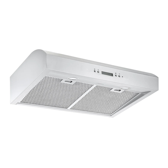
- Page 1 Undercabinet Range Hood 30 in. with Night Light AN-1253 User Manual & Installation Instructions IMPORTANT SAFETY INSTRUCTIONS Carefully read the important information regarding installation, safety and maintenance. Keep these instructions for future reference. 2019-08-29...
-
Page 2: Before You Begin
Before You Begin INSTALLERS - Start Here Safety Instructions are on pages 4 to 6 and Installation Instructions are on pages 9 to 18. Please perform these steps: 1. Read the safety instructions. 2. Read all instructions in the Installation section of this manual BEFORE installing the range hood. -
Page 3: Table Of Contents
Table of Contents Before You Begin ..........................2 Table of Contents ..........................3 Important Safety Information ......................4 Included Parts ........................... 7 Range Hood Dimensions ........................8 Specifications ............................ 8 Installation ............................9 Step 1 - Read the Safety Instructions .................... 9 Step 2 - Unpack Range Hood and Prepare Tools ................ -
Page 4: Important Safety Information
Important Safety Information READ ALL INSTRUCTIONS BEFORE USE Read and follow all instructions before using the range hood to prevent the risk of fire, electric shock, personal injury, or damage when using the range hood or appliances with the range hood. This guide does not cover all possible conditions that may occur. - Page 5 Important Safety Information WARNING: TO REDUCE RISK OF A RANGE To reduce the risk of injury to persons in the TOP GREASE FIRE: event of a gas leaks: a) Never leave surface units unattended at high • Extinguish any open flame. settings. Boilovers cause smoking and greasy •...
- Page 6 Important Safety Information WARNING: TO REDUCE RISK OF A RANGE 7. Two installers are recommended because of TOP GREASE FIRE: the large size and weight of this hood. 1. To reduce risk of fire and to properly exhaust 8. This product is equipped with a thermostat air, be sure to duct air outside. Do not vent which may start blower automatically.
-
Page 7: Included Parts
Included Parts Range Hood Vent-round Ø 6 in. (15.3 cm) Vent-rectangle 10 in. (25.4 cm) (Optional 14 in. (35.5 cm) available) 2 Filters Metal Inlet Cover Mounting Screws Vent Black Mounting Screws 3 pieces wire connector (ST4 x 8 mm) 9 + 1 pieces (ST4 x 8 mm) 4 + 1 pieces Hardware Note: For safety reasons, range hood mounting screws and anchors will not be included due to the variation of cabinetry constructions and wall material. -
Page 8: Range Hood Dimensions
Range Hood Dimensions 8 cm (3.1 in.) 76 cm (29.9 in) 25 cm / 35.4 cm (9.8 in. / 13.9 in.) 8 / 8.1 cm (3.1 / 3.1 in.) Specifications Body Design Stainless Steel Power Rating 120 V / 60 Hz (cETLus Certified) Total Input Power 200 W (195 W + 2 x 2.5 W) Motor Input Power 195 W... -
Page 9: Installation
Installation STEP 1 Read the Safety Instructions • It is very important to read the safety instructions on pages 4, 5 and 6. IMPORTANT: It is the installer’s responsibility to comply with installation clearances. STEP 2 Unpack Range Hood and Prepare Tools •... -
Page 10: Step 5 - Venting Installation Guidelines
Installation STEP 5 Venting Installation Guidelines • The following steps are for exterior ventilation. IMPORTANT: For the most efficient and quiet operation: • Vent system must terminate to the outside (roof or side wall). • It is recommended that the range hood be vented • DO NOT terminate the vent system in an attic or other vertically through the roof through 6 in. - Page 11 Installation IMPORTANT: electric cook tops and minimum of 30-inch (76.2 cm) • A minimum of 6 in. (15.3 cm) round or 3-1/4 x 10 in. (25.4 for gas stove tops and no higher than 30-inch (76.2 cm) cm x 8.3 cm) rectangular duct must be used to maintain for electric cook tops.
-
Page 12: Step 6 - Preparations
Installation STEP 6 Preparations NOTE: To avoid damage to your hood, prevent debris from entering the vent opening. • Determine and mark the centre line on the ceiling or wall where the range hood will be installed. • Make sure there is proper clearance within the ceiling or wall for exhaust vent. •... -
Page 13: Step 9 - Attaching Vent
Installation STEP 9 Attaching Vent • There are two venting ways, with two type of damper options, one is 6 inch (15.3 cm) round, another is 10 inch or 14 inch (25.4 or 35.5 cm) rectangle. NOTE: Please only punch the vent hole you want to use. Do not punch more than one vent hole, otherwise, the air power suction will be greatly affected. - Page 14 Installation Top venting using rectangular damper: • If you require rectangular top (vertical) venting, simply install the rectangular damper provided (See Fig #7, #8 and #9). Use four screws (ST4 x 8 mm) to connect 10 inch damper or eight screws (ST4 x 8 mm) for 14 inch damper. For 10 inch rectangular vent, keep these two parts.
-
Page 15: Step 10 - Installing The Hood
Installation STEP 10 Installing the Hood Method 1: Attaching the unit to the wall • Remove eight screws (4 x 8 mm) holding cover pan to hood, see Fig #13 and #14. Fig #13 Fig #14 • Mark or drill four small holes on the mounting position according to the dimensions on Fig #15. Fig #15 •... - Page 16 Installation Method 2: Attaching the unit to under kitchen cabinets • Mark or drill four small holes on the mounting position according to the space and dimensions cited on the following image (Fig #18). • tighten the screws to cabinet. •...
-
Page 17: Step 11 - Venting
Installation STEP 11 Venting • Depending on exterior ventilation chosen (see page 10), either exit the ducting through the ceiling or wall. • Always use rigid type metal/aluminum duct tube (follow the building codes in your area) to maximize airflow. Make sure that the backdraft flaps can open, to allow maximum airflow. Connect the duct tube to the vent/damper and securely seal with certified aluminum or foil tape so that it is air tight. Please check the building codes in your city to learn which tape product is recommended. -
Page 18: Step 12 - Install Filters
Installation STEP 12 Install Filters To install filters, follow four steps below (See Fig #23): • Angle the filter into slots at the back of the hood. • Push the button on handle of the filter. • Release the handle once the filter fits into a resting position. •... -
Page 19: Operation
Operation Lamp Speed Timer Power Timer Lamp Speed Power NOTE: When the hood has been initially connected to the power or after a power failure, all indicators and LCD display (with 4 speed setting + boost mode) turn ON for 1 second then OFF, the hood is in standby condition. -
Page 20: Maintenance
Maintenance Replacing the Light Pucks IMPORTANT: ALWAYS SWITCH OFF THE ELECTRICITY SUPPLY AT THE MAIN PANEL BEFORE CARRYING OUT ANY OPERATION ON THE APPLIANCE. Make sure the range hood is unplugged or turn OFF breaker. Remove filters and easy clean panel, push the spring, pull out the LED puck and unplug it. -
Page 21: Range Hood Assembly
Range Hood Assembly Range Hood Assembly Number Part Number Part Vent-round kit Vent-round kit Rectangle outlet Rectangle outlet Housing assembly Housing assembly Control bracket Control bracket Control board Control board Control box Control box Transformer Transformer Base of electronic box Base of electronic box Capacitor Cover of electronic box... -
Page 22: Assembly
Assembly Circuit Diagram Motor Transformer 0V 60Hz Capacitor CN10 Main PCB Motor LED Pucks MAX 10.2V 250mA 2.5W Temperature Humidity Sensor (Optional) Blower Assembly Number Part Bracket of motor Motor Blower Propeller Electrical Assembly Number Part Transformer Base of electronic box Capacitor Cover of electronic box —... -
Page 23: Troubleshooting
Troubleshooting Problem Cause Solution Light on, but motor does not The motor blocked Get rid of the blocking work The capacitor is damaged Have capacitor replaced The motor bearings are jammed Have motor replaced or damaged Light does not work, motor does Beside the mentioned above, check the following: not work Light is damaged... -
Page 24: Use And Care Information
Use and Care Information Operations • Read and understand all instructions and warnings in this manual before operating the appliance. Save these instructions for future reference. • Always leave safety grills and filters in place. Without these components, operating fans could catch on to hair, fingers and loose clothing. - Page 25 Ancona is in association with Mr Appliance for all after sales service calls. Please contact their service provider or visit their website: Phone: 1-888-998-2011 Website: www.mrappliance.com © 2019 Copyright of Ancona Home. All rights reserved. This material may not be reproduced, displayed, modified or distributed. — 25 —...
- Page 26 Notes — 26 —...
Need help?
Do you have a question about the AN-1253 and is the answer not in the manual?
Questions and answers