Table of Contents

Subscribe to Our Youtube Channel
Related Manuals for Icom IF3061S


Summary of Contents for Icom IF3061S
- Page 1 INSTRUCTION MANUAL VHF TRANSCEIVER iF3061T/S iF3063T/S UHF TRANSCEIVER iF4061T/S iF4063T/S This device complies with Part 15 of the FCC Rules. Operation is subject to the condition that this device does not cause harmful interference.
-
Page 2: Explicit Definitions
IC-F3061T/S/F3063T/S VHF TRANSCEIVERS and NOTE of personal injury, fire or electric shock. IC-F4061T/S/F4063T/S UHF TRANSCEIVERS. Icom, Icom Inc. and the logo are registered trademarks of Icom Incorporated (Japan) in the United States, the United Kingdom, Germany, France, Spain, Russia and/or other countries. -
Page 3: Table Of Contents
TABLE OF CONTENTS IMPORTANT ................ i 6 BATTERY CHARGING .......... 18–22 ■ Caution ..............18 EXPLICIT DEFINITIONS ............. i ■ Optional battery chargers ......... 20 TABLE OF CONTENTS ............ii PRECAUTIONS ..............iii 7 BATTERY CACE ............23 1 ACCESSORIES ............1–3 8 SWIVEL BELT CLIP .......... -
Page 4: Precautions
CAUTION: Changes or modifications to this transceiver, not tery pack. expressly approved by Icom Inc., could void your authority to operate this transceiver under FCC regulations. DO NOT push [PTT] when not actually desiring to trans- mit. -
Page 5: Accessories
ACCESSORIES ■ Supplied accessories ■ Accessory attachments D Flexible antenna The following accessories are supplied: Qty. q Flexible antenna …………………………………………… 1 Connect the supplied flexible anten- w Battery pack ……………………………………………… 1 na to the antenna connector. e Belt clip …………………………………………………… 1 r Connector cover (with screw) ………………………... - Page 6 ACCESSORIES D Belt clip ï Battery pack To attach the battery pack: To attach the belt clip: q Release the battery pack if it is attached. Slide the battery pack in the direction of the arrow (q), then w Slide the belt clip in the direction of the arrow until the belt lock it with the battery release button.
- Page 7 ACCESSORIES ï Connector cover Attach the connector cover when the optional speaker-micro- phone or head-set is not used. To detach the connector cover: To attach the connector cover: q Insert the connector cover into the multi-connector. q Unscrew the screw using a phillips screwdriver. w Detach the connector cover for the speaker-microphone or w Tighten the screw.
-
Page 8: Panel Description
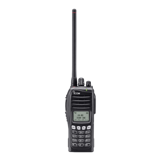
PANEL DESCRIPTION ■ Front panel e DEALER-PROGRAMMABLE KEY [Emer] Desired functions can be programmed by your dealer. ((☞ p. 7)) r DEALER-PROGRAMMABLE KEY [Side1] Desired functions can be programmed by your dealer. Speaker ((☞ p. 7)) t PTT SWITCH [PTT] Push and hold to transmit;... - Page 9 PANEL DESCRIPTION !0 MULTI-CONNECTOR Connect an optional speaker-microphone. Connector cover NOTE: Attach the connector cover when the optional speak- er-microphone is not used. See ((☞ p. 3)) for details. !1 BUSY/TRANSMIT INDICATOR ➥ Lights green while receiving a signal, or when the squelch is open.
-
Page 10: Function Display
PANEL DESCRIPTION ■ Function display t SCRAMBLER INDICATOR Appears when the voice scrambler function is activated. y BELL INDICATOR Appears/blinks when the specific 2-tone/DTMF select call is received, according to the pre-programming. u CALL CODE MEMORY INDICATOR Appears when the call code memory is selected. i BATTERY INDICATOR Appears or blinks when the battery power decreases to a CALA TXCU TXC... -
Page 11: Programmable Function Keys
[Side2], [Side3], [P0], [P1], [P2] and [P3] programmable function keys. ting. Consult your Icom dealer or system operator for details con- When the power ON scan function is turned OFF; cerning your transceivers programming. Push to start and cancel scanning operation. In case of If the programmable function names are bracketed in the fol- transmission during scan, cancels scanning. - Page 12 PANEL DESCRIPTION SCAN ADD/DEL (TAG) KEY “S S C C A A D D ” HIGH/LOW KEY “H H / / L L ” Push to add or delete the selected channel to/from the scan Push to select the transmit output power temporarily or per- group.
- Page 13 PANEL DESCRIPTION CALL KEYS “C C A A L L L L ” “C C A A L L A A ” “C C A A L L B B ” SCRAMBLER FUNCTION “S S C C R R ” Push to transmit a 2-tone.
-
Page 14: Basic Operation
BASIC OPERATION ■ Turning power ON D Battery type selection Prior to using the transceiver for the first time, the battery pack must be fully charged for optimum life and operation. The battery type must be selected according to the attaching ((☞p. -
Page 15: Channel Selection
BASIC OPERATION ■ Channel selection ■ Call procedure Several types of channel selections are available. Methods When your system employs tone signaling (excluding CTCSS may differ according to your system set up. and DTCS), the call procedure may be necessary prior to voice transmission. -
Page 16: Ltr Operation
LTR OPERATION ■ Receiving a call D Group call D Phone call q Push [CH Up] or [CH Down], or rotate [ROTARY SELEC- • Receive a phone call q Push [CH Up] or [CH Down], or rotate [ROTARY SELEC- TOR]* to select the LTR system channel or talk group. w When a call is received;... -
Page 17: Transmitting A Call
LTR OPERATION ■ Transmitting a call D Group call q Push [CH Up] or [CH Down], or rotate [ROTARY SELEC- • Make a phone call q Select the phone channel of LTR system channel. TOR]* to select the LTR system channel or talk group. w While pushing and holding [PTT], speak into the micro- •... -
Page 18: Conventional Operation
CONVENTIONAL OPERATION ■ Receiving and transmitting D Transmitting notes NOTE: Transmitting without an antenna may damage the transceiver. See ((☞ p. 1)) for accessory attachments. • Transmit inhibit function The transceiver has several inhibit functions which restrict Receiving: transmission under the following conditions: q Rotate [VOL] to turn the power ON. - Page 19 CONVENTIONAL OPERATION D TX code channel selection D DTMF transmission If the transceiver has [TX Code CH Select] assigned to it, the If the transceiver has [DTMF Autodial] assigned to it, the auto- indication can be toggled between the operating channel matic DTMF transmission function is available.
-
Page 20: User Set Mode
CONVENTIONAL OPERATION ■ User set mode ■ Emergency transmission User set mode is accessed at power ON and allows you to When [Emergency Single] or [Emergency Repeat] is pushed, set seldom-changed settings. In this case you can “cus- an emergency signal is automatically transmitted for the spec- tomize”... -
Page 21: Stun Function
CONVENTIONAL OPERATION ■ Stun function When the specified ID, set as a killer ID, is received, the stun function is activated. When the killer ID is received, the transceiver switches to the password required condition. Entering of the password via the keypad is necessary to operate the transceiver again in this case. -
Page 22: Battery Charging
Icom radios or Icom charger. Only Icom battery • R DANGER! DO NOT expose the battery to rain, snow, packs are tested and approved for use and charge with Icom seawater, or any other liquids. Do not charge or use a wet radios or Icom charger. - Page 23 • R DANGER! NEVER charge the battery pack in areas with abnormal odor, heats up, or is discolored or deformed. If any of these conditions occur, contact your Icom dealer or dis- extremely high temperatures, such as near fires or stoves, tributor.
-
Page 24: Optional Battery Chargers
BATTERY CHARGING ■ Optional battery chargers ï Rapid charging with the BC-160 ï AD-106 installation q Install the AD-106 desktop charger adapter into the holder The optional BC-160 provides rapid charging of optional Li- Ion battery packs. space of the BC-119N/BC-121N. w Connect the plugs of the BC-119N/BC-121N to the AD-106 •... - Page 25 BATTERY CHARGING ï Rapid charging with the BC-119N+AD-106 ï Rapid charging with the BC-121N+AD-106 The optional BC-119N provides rapid charging of battery The optional BC-121N allows up to 6 battery packs to be packs. The following items are additionally required. charged simultaneously.
- Page 26 BATTERY CHARGING IMPORTANT!: Battery charging caution Ensure the guide lobs on the battery pack are correctly aligned with the guide rails inside the charger adapter. (This illustration is described with the BC-160.) Lobs Guide rail...
-
Page 27: Battery Cace
BATTERY CASE ■ Optional battery case (BP-240) When using the optional battery case attached to the trans- Fig.1 ceiver, install 6 × AAA (LR03) size alkaline batteries as illus- BP-240 trated at right. q Unhook the battery cover release hook (q), and open the cover in the direction of the arrow (w). -
Page 28: Swivel Belt Clip
SWIVEL BELT CLIP ■ MB-93 contents e Clip the belt clip to a part of your belt. And insert the trans- ceiver into the belt clip until the base clip inserted fully into the groove. Qty. q Belt clip ……………………………………………………… 1 w Base clip ……………………………………………………... -
Page 29: Detaching
SWIVEL BELT CLIP ■ Detaching q Turn the transceiver upside down in the direction of the w Release the battery pack if it is attached. ((☞ p. 2)) e Pinch the clip (q), and slide the base clip in the direction arrow and pull out from the belt clip. -
Page 30: Options
OPTIONS D BATTERY PACK D BELT CLIPS Battery pack Voltage Capacity Battery life • MB-93 SWIVEL BELT CLIP • MB-94 BELT CLIP 7.4 V 1150 mAh 8 hrs. BP-231 Exclusive alligator-type belt clip. The same as supplied with the transceiver. 7.4 V 2000 mAh 15 hrs. - Page 31 OPTIONS D OTHER OPTIONS ï About VS-1SC VOX / PTT CASE The VS-1SC is a VOX/PTT unit for Icom handheld trans- • SP-13 EARPHONE Provides clear receive audio in noisy environment. ceivers, and allows you hands-free operation. An optional headset (HS-94, etc.) is required for operation.
- Page 32 OPTIONS VOX gain and delay adjustment • VOX Delay q Attach the connector of the VS-1SC into the multi-connec- The VOX delay time can be set from 0.5 to 3.0 sec. (0.5 sec. tor on the transceiver and tighten the screw. step) for a convenient interval before returning to receive.
-
Page 33: Safety Training Information
• ALWAYS keep the antenna at least 2.5 cm (1 inch) away to Radio Frequency Electromagnetic Fields, 3 kHz to 300 from the body when transmitting and only use the Icom belt- GHz. clips listed on page 26 when attaching the radio to your belt, •... - Page 34 SAFETY TRAINING INFORMATION Electromagnetic Interference/Compatibility During transmissions, your Icom radio generates RF energy that can possibly cause interference with other devices or systems. To avoid such interference, turn off the radio in areas where signs are posted to do so. DO NOT operate the transmitter in areas that are sensitive to electromagnetic radiation such as hospitals, aircraft, and blasting sites.
- Page 35 MEMO...
- Page 36 A-6488D-1EX-q Printed in Japan 1-1-32 Kamiminami, Hirano-ku, Osaka 547-0003, Japan © 2006 Icom Inc.
Need help?
Do you have a question about the IF3061S and is the answer not in the manual?
Questions and answers