
Related Manuals for Velleman 2298892


Summary of Contents for Velleman 2298892
- Page 1 DVM902 CAT II 700 V / CAT IV 600 V USER MANUAL HANDLEIDING MODE D'EMPLOI MANUAL DEL USUARIO BEDIENUNGSANLEITUNG INSTRUKCJA OBSŁUGI MANUAL DO UTILIZADOR...
- Page 2 DVM902 V. 02 – 29/01/2020 ©Velleman nv...
- Page 3 Respect the local environmental rules. If in doubt, contact your local waste disposal authorities. Thank you for choosing Velleman! Please read the manual thoroughly before bringing this device into service. If the device was damaged in transit, do not install or use it and contact your dealer.
-
Page 4: General Guidelines
DVM902 Continuity 3. General Guidelines ® Refer to the Velleman Service and Quality Warranty on the last pages of this manual. This symbol indicates: Read instructions Not reading the instructions and manual can lead to damage, injury or death. This symbol indicates: Danger A hazardous condition or action that may result in injury or death. -
Page 5: Maintenance
Never exceed the limit value for protection. This limit value is listed separately in the specifications for each range of measurement. • Do not touch unused terminals when the meter is linked to a circuit which is being tested. V. 02 – 29/01/2020 ©Velleman nv... -
Page 6: General Description
DMMs are categorized depending on the risk and severity of transient overvoltage that might occur at the point of test. Transients are short-lived bursts of energy induced in a system, e.g. caused by lightning strike on a power line. V. 02 – 29/01/2020 ©Velleman nv... -
Page 7: Pollution Degree
DVM indicates in which environment the device may be used. Pollution No pollution or only dry, nonconductive pollution occurs. The degree 1 pollution has no influence. (only to be found in hermetically sealed enclosures) V. 02 – 29/01/2020 ©Velleman nv... -
Page 8: Specifications
............1 x 3.7 V (incl.) display ............. LCD, 6000 counts ranging mode ............auto/manual continuity buzzer ..............yes diode test ................yes low-battery indication ............yes data hold ................yes backlight ................yes V. 02 – 29/01/2020 ©Velleman nv... - Page 9 ± (0.8 % + 3) 600 V 100 mV 700 V ± (1.2 % + 3) AC true RMS Frequency range: 40 Hz-2 kHz Overload protection: 700 V DC or AC rms Impedance: 10 MΩ V. 02 – 29/01/2020 ©Velleman nv...
- Page 10 6 kΩ 1 Ω 60 kΩ 10 Ω ± (1.0 % + 2) 6 MΩ 1 kΩ 60 MΩ 10 kΩ ± (1.5 % + 3) Overload protection: 700 V DC or AC rms V. 02 – 29/01/2020 ©Velleman nv...
- Page 11 DC current ± 1.5 mA approximate forward reversed DC voltage ± 4 V voltage of the diode built-in buzzer sounds open-circuit voltage ± 2 V if resistance < 50 Ω Overload protection: 700 V DC or AC rms V. 02 – 29/01/2020 ©Velleman nv...
-
Page 12: Duty Cycle
± (3 % + 3) NiCr-NiSi sensor Overload protection: 700 V DC or AC rms 9.11 NON-CONTACT AC VOLTAGE DETECTION (NCV) Test voltage range: 90-1000 V AC rms The built-in buzzer will sound when live voltage is detected. V. 02 – 29/01/2020 ©Velleman nv... -
Page 13: Operation
Open the circuit in which the current is to be measured and connect the test leads to the circuit IN SERIES. Read the current value and the polarity of the red lead connection on the LCD display. V. 02 – 29/01/2020 ©Velleman nv... -
Page 14: Resistance Measurement
The approx. forward voltage drop of the diode will be displayed. For measuring continuity, connect the test leads to two points of the circuit to be tested. If continuity exists, the built-in buzzer will sound. V. 02 – 29/01/2020 ©Velleman nv... -
Page 15: Frequency And Duty Cycle Measurement
These sources may trigger NCV detection and invalidate the test. 10.9 DATA HOLD In any range, press HOLD to lock the display value. The DH sign will appear on the display. Press again to exit. V. 02 – 29/01/2020 ©Velleman nv... -
Page 16: Max/Min Hold
Fuses: F0.8 A/1000 V, 6.75 x 33 mm, F15 A/1000 V, 6.75 x 33 mm Make sure the meter is closed tight and put the protective edge back in place before using the meter. V. 02 – 29/01/2020 ©Velleman nv... -
Page 17: Troubleshooting
The information in this manual is subject to change without prior notice. © COPYRIGHT NOTICE The copyright to this manual is owned by Velleman nv. All worldwide rights reserved. No part of this manual may be copied, reproduced, translated or reduced to any electronic medium or otherwise without the prior written consent of the copyright holder. - Page 18 Waarschuwing: gevaarlijke toestand of actie die kan leiden tot letsel of de dood Opgelet: Een onvoorzichtig gebruik kan de multimeter of het toestel dat u wilt testen beschadigen. Dubbele isolatie (klasse II-bescherming) Aarding Zekering Condensator V. 02 – 29/01/2020 ©Velleman nv...
-
Page 19: Algemene Richtlijnen
DVM902 Diode Continuïteit 3. Algemene richtlijnen Raadpleeg de Velleman ® service- en kwaliteitsgarantie achteraan deze handleiding. Dit symbool betekent Instructies lezen Het niet lezen van deze instructies en de handleiding kan leiden tot beschadiging, letsel of de dood. Dit symbool betekent Gevaar Gevaarlijke toestand of actie die kan leiden tot letsel of de dood. -
Page 20: Tijdens Het Gebruik
• Overschrijd nooit de grenswaarden. Deze waarde wordt afzonderlijk in de technische gegevens van elk meetbereik vermeld. • Raak geen ongebruikte aansluitingen aan wanneer de meter gekoppeld is aan een meetcircuit. V. 02 – 29/01/2020 ©Velleman nv... - Page 21 DMM’s worden opgedeeld volgens het risico op en de ernst van spanningspieken die kunnen optreden op het meetpunt. Spanningspieken zijn kortstondige uitbarstingen van energie die geïnduceerd worden in een systeem door bv. blikseminslag op een hoogspanningslijn. V. 02 – 29/01/2020 ©Velleman nv...
- Page 22 De opgegeven waarde van vervuilingsgraad geeft aan in welke omgeving dit apparaat veilig gebruikt kan worden. Vervuilingsgraad Omgeving zonder, of met enkel droge, niet-geleidende vervuiling. De vervuiling heeft geen invloed. (komt enkel voor in hermetisch afgesloten ruimtes) V. 02 – 29/01/2020 ©Velleman nv...
- Page 23 F15 A/1000 VDC, 6.75 x 33 mm voeding ............1x 3.7 V (meegelev.) display ............. LCD, 6000 counts bereikmodus ..........automatisch + manueel continuïteitszoemer ..............ja diodetest ................. ja batterij-laag-indicatie ..............ja dataholdfunctie ................ ja V. 02 – 29/01/2020 ©Velleman nv...
- Page 24 ± (0.8 % + 3) 600 V 100 mV 700 V ± (1.2 % + 3) AC true RMS Frequentiebereik: 40 Hz-2 kHz Beveiliging tegen overbelasting: 700 V DC of AC rms Impedantie: 10 MΩ V. 02 – 29/01/2020 ©Velleman nv...
- Page 25 6 kΩ 1 Ω 60 kΩ 10 Ω ± (1.0 % + 2) 6 MΩ 1 kΩ 60 MΩ 10 kΩ ± (1.5 % + 3) Beveiliging tegen overbelasting: 700 V DC of AC rms V. 02 – 29/01/2020 ©Velleman nv...
- Page 26 DC-doorlaatstroom ± 1,5 mA van de diode bij DC-sperspanning ± 4 V benadering ingebouwde zoemer bij weerstanden nullastspanning ± 2 V < 50 Ω Beveiliging tegen overbelasting: 700 V DC of AC rms V. 02 – 29/01/2020 ©Velleman nv...
- Page 27 303 tot 1832 °F ± (3 % + 3) NiCr-NiSi-sensor Beveiliging tegen overbelasting: 700 V DC of AC rms 9.11 CONTACTLOZE AC-METING (NCV) Testbereik spanning: 90-1000 V AC rms De ingebouwde zoemer klinkt bij aanwezige spanning. V. 02 – 29/01/2020 ©Velleman nv...
- Page 28 “COM”-bus. Sluit het rode meetsnoer aan op de "15A"-bus voor metingen tussen 600mA en 15A). Druk op SELECT en selecteer de “DC”- of “AC”-meting. Sluit de meetsnoeren IN REEKS aan op het circuit waarvan u de belasting wilt meten. V. 02 – 29/01/2020 ©Velleman nv...
- Page 29 Voor continuïteitsmeting, sluit de meetsnoeren aan op de twee punten van het circuit dat u wilt meten. De ingebouwde zoemer weerklinkt als er continuïteit is V. 02 – 29/01/2020 ©Velleman nv...
- Page 30 10.9 DATA HOLD Druk op HOLD om de uitgelezen waarde te vergrendelen. Het DH-symbool verschijnt op het scherm. Druk nogmaals om te verlaten. Druk nogmaals om te verlaten. V. 02 – 29/01/2020 ©Velleman nv...
-
Page 31: Max/Min Hold
Sluit de behuizing en draai de schroef vast. Batterij: 1x 3.7 V. Respecteer de polariteit Zekeringen: F0.8 A/1000 V, 6.75 x 33 mm, F15 A/1000 V, 6.75 x 33 mm Sluit de behuizing zorgvuldig. V. 02 – 29/01/2020 ©Velleman nv... -
Page 32: Problemen En Oplossingen
(tip: Vermindert de lichtsterkte van de achtergrondverlichting/LCD-display, dan is de batterij bijna leeg.) Gebruik dit toestel enkel met originele accessoires. Velleman nv is niet aansprakelijk voor schade of kwetsuren bij (verkeerd) gebruik van dit toestel. Voor meer informatie over dit product en de laatste versie van deze handleiding, zie www.velleman.eu. - Page 33 Avertissement : une situation ou action dangereuse pouvant causer des blessures ou entraîner la mort Attention : une situation ou action dangereuse pouvant endommager l'appareil ou l'équipement à mesurer Isolation double (classe de protection II) Terre Fusible V. 02 – 29/01/2020 ©Velleman nv...
-
Page 34: Directives Générales
DVM902 Condensateur Diode Continuité 3. Directives générales Se référer à la garantie de service et de qualité Velleman ® en fin de ce mode d'emploi. Ce symbole indique : Lire les instructions Ne pas lire les instructions ou le mode d'emploi peut causer des endommagements ou blessures, ou entraîner la mort. -
Page 35: Entretien
Ne pas utiliser des solvants ou des produits abrasifs. Nettoyer avec un chiffon humide et un détergent doux. 5. Pendant l'utilisation Risque de choc électrique pendant l’opération. Être prudent lorsque vous effectuez des mesures sur un circuit sous tension. V. 02 – 29/01/2020 ©Velleman nv... -
Page 36: Description Générale
Borne “COM” Connecter le cordon de mesure noir (-). Borne “µAmA” Connecter le cordon de mesure rouge (+) à ce connecter pour mesurer le courant (sauf 15 A). V. 02 – 29/01/2020 ©Velleman nv... -
Page 37: Degré De Pollution
8. Degré de pollution La norme IEC 61010-1 spécifie les différents types de pollution environnementale, chaque type nécessitant son propre niveau de protection afin de garantir la sécurité. Un environnement rude nécessite un niveau de V. 02 – 29/01/2020 ©Velleman nv... -
Page 38: Spécifications
F0.8 A/1000 VDC, 6.75 x 33 mm F15 A/1000 VDC, 6.75 x 33 mm alimentation ............1 x 3.7 V (incl.) écran ..............LCD, 6000 points sélection de plage ........automatique + manuel V. 02 – 29/01/2020 ©Velleman nv... -
Page 39: Tension Alternative
± (0.8 % + 3) 600 V 100 mV 700 V ± (1.2 % + 3) AC true RMS Plage de fréquence: 40 Hz-2 kHz Protection de surcharge : 700 V CC ou CA rms Impédance: 10 MΩ V. 02 – 29/01/2020 ©Velleman nv... - Page 40 1 Ω 60 kΩ 10 Ω ± (1.0 % + 2) 6 MΩ 1 kΩ 60 MΩ 10 kΩ ± (1.5 % + 3) Protection de surcharge : 700 V CC ou CA rms V. 02 – 29/01/2020 ©Velleman nv...
- Page 41 CC ± 4 V diode le ronfleur intégré s'active lorsque la tension à circuit ouvert ± 2 V résistance < ± 50 Ω Protection de surcharge : 700 V CC ou CA rms V. 02 – 29/01/2020 ©Velleman nv...
-
Page 42: Cycle De Service
Protection de surcharge : 700 V CC ou CA rms 9.11 DÉTECTION DE TENSION SANS CONTACT (NCV) Plage de tension : 90-1000 V AC rms Le ronfleur intégré s'active lors de la détection d'une tension. V. 02 – 29/01/2020 ©Velleman nv... - Page 43 à la borne “COM” jack (connecter le cordon de mesure rouge à la borne "15A" pour des mesures entre 600 mA et 15 A). Enfoncer SELECT pour sélectionner le mesurage “DC” ou “AC”. V. 02 – 29/01/2020 ©Velleman nv...
- Page 44 Pour la mesure de diode, connecter le cordon de mesure rouge à l'anode et le cordon de mesure noir à la cathode de la diode. Le ronfleur intégré s'active en cas de continuité. V. 02 – 29/01/2020 ©Velleman nv...
- Page 45 à intensité variable, moteurs, etc.) lors de l'utilisation. Ces sources peuvent activer la détection NCV et annuler le mesurage. 10.9 DATA HOLD Enfoncer HOLD pour bloquer la valeur sur l'afficheur. Le symbole DH s'affiche. Appuyer à nouveau pour quitter. V. 02 – 29/01/2020 ©Velleman nv...
-
Page 46: Max/Min Hold
Pile: 1x 3.7 V. Respecter la polarité Fusible: F0.8 A/1000 V, 6.75 x 33 mm, F15 A/1000 V, 6.75 x 33 mm Avant d'utiliser le multimètre, s'assurer que le panneau arrière est bien fermé. V. 02 – 29/01/2020 ©Velleman nv... -
Page 47: Problèmes Et Solutions
être modifiés sans notification préalable. © DROITS D’AUTEUR Velleman SA est l’ayant droit des droits d’auteur de ce mode d'emploi. Tous droits mondiaux réservés. Toute reproduction, traduction, copie ou diffusion, intégrale ou partielle, du contenu de ce mode d'emploi par quelque procédé... -
Page 48: Manual Del Usuario
Si tiene dudas, contacte con las autoridades locales para residuos. ¡Gracias por elegir Velleman! Lea atentamente las instrucciones del manual antes de usar el aparato. Si ha sufrido algún daño en el transporte no lo instale y póngase en contacto con su distribuidor. -
Page 49: Normas Generales
DVM902 Diodo Continuidad 3. Normas generales Véase la Garantía de servicio y calidad Velleman ® al final de este manual del usuario. Este símbolo indica: Leer las instrucciones Si no lee las instrucciones o el manual del usuario puede dañar el aparato o sufrir heridas, incluso morir. -
Page 50: Mantenimiento
Riesgo de descarga eléctrica durante el funcionamiento. Sea cuidadoso al efectuar mediciones en un circuito bajo tensión. • Utilice sólo el aparato para aplicaciones descritas por el fabricante sino podría dañar los sistemas de protección. V. 02 – 29/01/2020 ©Velleman nv... -
Page 51: Descripción General
Conecte la punta de prueba roja a esta conexión para medir la tensión, la resistencia y la frecuencia. borne "COM" Conecte la punta de prueba negra (negativa). Borne “µAmA” Conecte la punta de prueba roja (positiva) a esta conexión para medir la corriente (salvo 15 A). V. 02 – 29/01/2020 ©Velleman nv... -
Page 52: Categoría De Sobretensión/Instalación
8. Grado de contaminación (Pollution degree) La norma IEC 61010-1 especifica los diferentes tipos de contaminación ambiental. Cada tipo necesita su propio nivel de protección para garantizar la seguridad. Un ambiente rugoso necesita un nivel de protección más V. 02 – 29/01/2020 ©Velleman nv... -
Page 53: Especificaciones
................700 V protección por fusible F0.8 A/1000 VDC, 6.75 x 33 mm F15 A/1000 VDC, 6.75 x 33 mm alimentación ..........1 x pila de 3.7 V (incl.) pantalla ............LCD, 6000 cuentas V. 02 – 29/01/2020 ©Velleman nv... - Page 54 ± (0.8 % + 3) 600 V 100 mV 700 V ± (1.2 % + 3) AC true RMS Rango de frecuencias: 40 Hz-2 kHz Protección de sobrecarga: 700 V DC o AC rms Impedancia: 10 MΩ V. 02 – 29/01/2020 ©Velleman nv...
- Page 55 6 kΩ 1 Ω 60 kΩ 10 Ω ± (1.0 % + 2) 6 MΩ 1 kΩ 60 MΩ 10 kΩ ± (1.5 % + 3) Protección de sobrecarga: 700 V DC o AC rms V. 02 – 29/01/2020 ©Velleman nv...
- Page 56 DC ± 4 V del diodo. señal acústica en caso tensión de circuito abierto de una resistencia ± 2 V < 50 Ω Protección de sobrecarga: 700 V DC o AC rms V. 02 – 29/01/2020 ©Velleman nv...
-
Page 57: Ciclo De Trabajo
Protección de sobrecarga: 700 V DC o AC rms 9.11 DETECCIÓN DE TENSIÓN AC SIN CONTACTO (NCV) Rango de la tensión de prueba: 90-1000 V AC rms El zumbador emitirá una señal acústica en cuanto detecte una tensión. V. 02 – 29/01/2020 ©Velleman nv... - Page 58 "COM" (Conecte la punta de prueba roja al borne “15A” para mediciones entre 600 mA y 15 A). Pulse SELECT para seleccionar la medición “DC” o “AC”. Conecte las puntas de prueba EN SERIE al circuito del que quiere medir la corriente. V. 02 – 29/01/2020 ©Velleman nv...
-
Page 59: Medir La Resistencia
El multímetro visualizará la tensión directa aproximativa del diodo. Para la prueba de continuidad, conecte las puntas de prueba a dos puntas del circuito que quiere probar. El zumbador incorporado sonará si hay continuidad. V. 02 – 29/01/2020 ©Velleman nv... - Page 60 Estas podrían activar una detección NCV y anular la prueba. 10.9 RETENCIÓN DE LECTURA (DATA HOLD) En cualquier rango, pulse HOLD para fijar el valor en la pantalla. "DH" se visualizará en la pantalla. Vuelva a pulsar para salir. V. 02 – 29/01/2020 ©Velleman nv...
-
Page 61: Max/Min Hold
La pila: 1 x pila de 3.7 V. Respete la polaridad. Fusibles: F0.8 A/1000 V, 6.75 x 33 mm, F15 A/1000 V, 6.75 x 33 mm Antes de utilizar el multímetro, verifique que el panel trasero esté bien cerrado. V. 02 – 29/01/2020 ©Velleman nv... -
Page 62: Solución De Problemas
© DERECHOS DE AUTOR Velleman NV dispone de los derechos de autor para este manual del usuario. Todos los derechos mundiales reservados. Está estrictamente prohibido reproducir, traducir, copiar, editar y guardar este manual del usuario o partes de ello sin el consentimiento previo por escrito del propietario del copyright. - Page 63 Falls Zweifel bestehen, wenden Sie sich für Entsorgungsrichtlinien an Ihre örtliche Behörde. Vielen Dank, dass Sie sich für Velleman entschieden haben! Lesen Sie diese Bedienungsanleitung vor Inbetriebnahme sorgfältig durch. Überprüfen Sie, ob Transportschäden vorliegen. Sollte dies der Fall sein, verwenden Sie das Gerät nicht und wenden Sie sich an Ihren Händler.
-
Page 64: Allgemeine Richtlinien
Sicherung Kondensator Diode Durchgangsprüfung 3. Allgemeine Richtlinien ® Siehe Velleman Service- und Qualitätsgarantie am Ende dieser Bedienungsanleitung. Dieses Symbol bedeutet: Bitte lesen Sie die Hinweise Das nicht Lesen der Hinweise und der Bedienungsanleitung kann Schäden, Verletzungen oder den Tod verursachen. -
Page 65: Wartung
Es gibt keine zu wartenden Teile. Bestellen Sie eventuelle Ersatzteile bei Ihrem Fachhändler. Trennen Sie die Messleitungen vor dem Warten oder Reinigen von jeder Spannungsquelle. Informationen über den Batterie- und Sicherungswechsel finden Sie unter §11 Batterie- und Sicherungswechsel. V. 02 – 29/01/2020 ©Velleman nv... -
Page 66: Während Des Gebrauchs
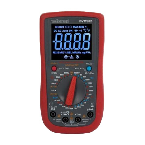
Siehe Abbildung, Seite 2 dieser Bedienungsanleitung: Display 3 ½-stellig, 7 Segmente, LCD Funktionsknöpfe Drehschalter "15A"-Anschlussbuchse Stecken Sie die rote (positive) Messleitung in diese Buchse, um einen max. Strom bis max. 15 A zu messen. V. 02 – 29/01/2020 ©Velleman nv... - Page 67 Dieses Gerät wurde gemäß der EN 61010-1 Überspannungskategorie CAT II 700 V und CAT IV 600 V entworfen. Dies beinhaltet bestimmte Anwendungsbeschränkungen in Bezug auf Spannungen und Spannungsspitzen, die in der Gebrauchsumgebung, vorkommen können. Siehe Liste oben. V. 02 – 29/01/2020 ©Velleman nv...
- Page 68 Warnung: Das Gerät wurde gemäß EN 61010-1 Verschmutzungsgrad 2 entworfen. Dies beinhaltet bestimmte Anwendungsbeschränkungen in Bezug auf die Verschmutzungsgrad, die in der Gebrauchsumgebung, vorkommen kann. Siehe Liste oben. Das Gerät eignet sich nur für die Anwendung in Umgebungen mit Verschmutzungsgrad 2. V. 02 – 29/01/2020 ©Velleman nv...
-
Page 69: Technische Daten
0.1 mV 1 mV ± (0.5 % + 2) 60 V 10 mV 600 V 100 mV 700 V ± (0.8 % + 2) Überlastschutz: 700 V DC oder AC rms Impedanz: 10 MΩ V. 02 – 29/01/2020 ©Velleman nv... - Page 70 10 mA ± (2.5 % + 5) AC true RMS Frequenzbereich: 40 Hz-2 kHz Überlastschutz: Sicherung (0.8 A / 700 V), Sicherung (F15 A / 700 V) Max. stationärer Strom bei kontinuierlichem Testen: 1 A V. 02 – 29/01/2020 ©Velleman nv...
- Page 71 Testbedingung Durchlassspannung DC-Durchlassstrom ± 1.5 mA der Diode wird im DC-Sperrspannung ± 4 V Display angezeigt. akustisches Signal bei Leerlaufspannung ± 2 V Widerstand < 50 Ω Überlastschutz: 700 V DC oder AC rms V. 02 – 29/01/2020 ©Velleman nv...
- Page 72 303 bis 1832 °F ± (3 % + 3) NiCr-NiSi-Sensor Überlastschutz: 700 V DC oder AC rms 9.11 BERÜHRUNGSLOSE WECHSELSPANNUNGSERKENNUNG (NCV) Prüfspannungsbereich: 90-1000 V AC rms Es ertönt ein akustisches Signal, wenn Spannung entdeckt wird. V. 02 – 29/01/2020 ©Velleman nv...
- Page 73 ” oder “ ”. Stecken Sie die rote Messleitung in die "µAmA"-Buchse und die schwarze Messleitung in die "COM"-Buchse (stecken Sie die rote Messleitung in die "15A"-Buchse für Messungen zwischen 600 mA und 15 A). V. 02 – 29/01/2020 ©Velleman nv...
-
Page 74: Diodentest Und Akustische Durchgangsprüfung
Anode der Diode und die schwarze Messleitung mit der Kathode. Die Durchlassspannung der Diode wird im Display angezeigt. Für die Durchgangsprüfung, verbinden Sie die Messleitungen mit zwei Punkten der Schaltung, die Sie messen möchten. Bei Durchgang ertönt ein akustisches Signal. V. 02 – 29/01/2020 ©Velleman nv... - Page 75 Diese Quellen können eine berührungslose Spannungsmessung und einen Fehltest auslösen. 10.9 DATA HOLD In jedem Bereich, drücken Sie auf HOLD, um den Wert im Display festzuhalten. DH erscheint auf dem Display. Drücken Sie wieder, um zu verlassen. V. 02 – 29/01/2020 ©Velleman nv...
-
Page 76: Max/Min Hold
Schließen Sie das Gehäuse und schrauben Sie die Schraube fest. Batterie: 1 x 3.7 V-Batterie. Legen Sie die Batterie polungsrichtig ein. Sicherungen: F0.8 A/1000 V, 6.75 x 33 mm, F15 A/1000 V, 6.75 x 33 mm Verschließen Sie das Gehäuse wieder sorgfältig. V. 02 – 29/01/2020 ©Velleman nv... -
Page 77: Problemlösung
(Hinweis: Verringert sich die Intensität der Hintergrundbeleuchtung/des LCD-Displays, dann ist die Batterie schwach.) Verwenden Sie dieses Gerät nur mit originellen Zubehörteilen. Velleman NV übernimmt keine Haftung für Schaden oder Verletzungen bei (falscher) Anwendung dieses Gerätes. Mehr Informationen zu diesem Produkt und die neueste Version dieser Bedienungsanleitung finden Sie hier: www.velleman.eu. -
Page 78: Instrukcja Obsługi
W razie wątpliwości należy skontaktować się z lokalnym organem odpowiedzialnym za utylizację odpadów. Dziękujemy za zakup produktu Velleman! Prosimy o dokładne zapoznanie się z instrukcją obsługi przed użyciem urządzenia. Nie montować ani nie używać urządzenia, jeśli zostało uszkodzone podczas transportu - należy skontaktować... -
Page 79: Informacje Ogólne
Unikać zbyt niskich i wysokich temperatur, jak również dużych wahań temperatury. W przypadku przenoszenia urządzenia z zimnego do ciepłego miejsca, pozostawić je wyłączone do momentu osiągnięcia temperatury pokojowej. Pomoże to zapobiec kondensacji i błędom pomiarowym. V. 02 – 29/01/2020 ©Velleman nv... - Page 80 4. Konserwacja W urządzeniu nie występują części, które mogą być serwisowane przez użytkownika. W sprawie serwisowania i/lub części zamiennych należy zwrócić się do autoryzowanego sprzedawcy. V. 02 – 29/01/2020 ©Velleman nv...
- Page 81 • Nie dokonywać pomiarów rezystancji, parametrów diod ani ciągłości w obwodach pod napięciem. Upewnić się, że wszystkie kondensatory w obwodzie zostały rozładowane. 6. Informacje ogólne Patrz rysunki na stronie 2 niniejszej instrukcji: V. 02 – 29/01/2020 ©Velleman nv...
- Page 82 Mierniki kategorii III są przeznaczone do pomiaru układów kategorii I i II oraz urządzeń jedno- lub wielofazowych, znajdujących KAT. się w odległości co najmniej 10 m od układu kategorii IV, oraz pomiaru parametrów sprzętu rozdzielczego (skrzynki bezpiecznikowe, obwody oświetleniowe, piecyki elektryczne). V. 02 – 29/01/2020 ©Velleman nv...
-
Page 83: Stopień Zanieczyszczenia
Występują zanieczyszczenia o właściwościach zanieczyszczenia przewodzących lub zanieczyszczenia suche bez właściwości przewodzących, które na skutek kondensacji mogą stać się przewodzące. (środowiska przemysłowe i mające kontakt z powietrzem zewnętrznym, ale chronione przed działaniem opadów atmosferycznych). V. 02 – 29/01/2020 ©Velleman nv... - Page 84 ..........od -20°C do 60°C wilgotność ............< 90 % RH sonda pomiarowa ..KAT. II 700 V/ KAT. IV 600 V, 15 A; L = 90 cm klasa IP ................IP20 V. 02 – 29/01/2020 ©Velleman nv...
-
Page 85: Prąd Stały Dc
± (1,2 % + 2) 600 mA 100 µA 15 A 1 mA ± (2,0 % + 3) Zabezpieczenie przeciążeniowe: bezpiecznik F0,8 A/700 V, bezpiecznik F15 A/700 V Maks. prąd ustalony testu ciągłego wynosi 1 A V. 02 – 29/01/2020 ©Velleman nv... -
Page 86: Prąd Zmienny Ac
99,99 µF 10 nF ± (5,0 % + 10) 999,9 µF 100 nF 9,999 mF 1 µF ± (10,0 % + 20) 99,99 mF 10 µF Zabezpieczenie przeciążeniowe: 700 V DC lub AC rms V. 02 – 29/01/2020 ©Velleman nv... - Page 87 Zabezpieczenie przeciążeniowe: 700 V DC lub AC rms 9.9 CYKL PRACY 0,1-99 %: ± (2,0 % + 2), częstotliwość < 10 kHz Czułość: sygnał sinusoidalny 0,6 V rms Zabezpieczenie przeciążeniowe: 700 V DC lub AC rms V. 02 – 29/01/2020 ©Velleman nv...
- Page 88 Uwagi • Jeżeli zakres nie jest znany, ustawić wysoki i stopniowo zmniejszać. • Przekroczenie zakresu jest sygnalizowane wyświetlaniem OL lub -OL. Ustawić wyższy zakres. • Maksymalny napięciem wejściowy wynosi 700 V rms. V. 02 – 29/01/2020 ©Velleman nv...
-
Page 89: Pomiar Rezystancji
Podłączyć czerwony przewód pomiarowy do gniazda “VHz”, a czarny do gniazda "COM”. Ustawić pokrętło odpowiedniej pozycji zakresu " ". Podłączyć przewody pomiarowe do testowanego źródła i odczytać wartość z wyświetlacza LCD. V. 02 – 29/01/2020 ©Velleman nv... -
Page 90: Test Diod I Ciągłości Obwodu
Podłączyć czerwony wtyk bananowy do gniazda "VHz”, a czarny do gniazda "COM”. Ustawić pokrętło w pozycji “°C/°F”. Nacisnąć SELECT, aby wybrać pomiar °C lub °F. Umieścić sondę w miejscu, w którym ma zostać dokonany pomiar i odczytać wynik z ekranu LCD. V. 02 – 29/01/2020 ©Velleman nv... - Page 91 11. Wymiana baterii i bezpiecznika UWAGA: Aby uniknąć porażenia prądem elektrycznym, przed otwarciem obudowy każdorazowo należy odłączyć przewody pomiarowe. Aby zapobiec zagrożeniu pożarowemu, używać wyłącznie bezpieczników o parametrach określonych w niniejszej instrukcji. Uwaga: patrz ostrzeżenie na gnieździe baterii V. 02 – 29/01/2020 ©Velleman nv...
-
Page 92: Wykrywanie I Usuwanie Usterek
© INFORMACJA O PRAWACH AUTORSKICH Właścicielem praw autorskich do niniejszej instrukcji jest firma Velleman nv. Wszelkie prawa są zastrzeżone na całym świecie. Żadna część niniejszej instrukcji nie może być kopiowana, powielana, tłumaczona ani przenoszona na jakikolwiek nośnik elektroniczny (lub w inny sposób) bez wcześniejszej pisemnej zgody właściciela praw autorskich. -
Page 93: Manual Do Utilizador
Advertência: uma situação ou procedimento de perigo podem causar lesões ou até mesmo a morte Atenção: condição ou ação que pode provocar danos no medidor ou equipamento a ser testado Duplo isolamento (proteção classe 2) Ligação à terra Fusível V. 02 – 29/01/2020 ©Velleman nv... -
Page 94: Normas Gerais
DVM902 Condensador Díodo Continuidade 3. Normas gerais Consulte a Garantia de Serviço e Qualidade Velleman ® na parte final deste manual do utilizador. Este símbolo indica: Ler as instruções Não ler as instruções ou o manual pode levar à ocorrência de danos, lesões ou até... -
Page 95: Durante A Utilização
Não utilize abrasivos ou solventes no medidor. Para efeitos de limpeza use um pano húmido e um detergente neutro. 5. Durante a Utilização Risco de choque eléctrico durante o funcionamento. Tenha muito cuidado ao medir circuitos sob tensão. V. 02 – 29/01/2020 ©Velleman nv... -
Page 96: Descrição Geral
Introduza cabo de teste vermelho (positivo) neste conector para medir a tensão, resistência e frequência. entrada “COM” Introduza o cabo de teste preto (negativo). ficha “µAmA” Introduza cabo de teste vermelho (positivo) neste conector para medir a corrente (except 15 A). V. 02 – 29/01/2020 ©Velleman nv... -
Page 97: Categorias De Sobretensão/Instalação
A norma IEC 61010-1 especifica os diferentes tipos de contaminação ambiental. Cada tipo necessita do seu próprio nível de protecção para garantir segurança. Um ambiente rugoso necessita de um nível de protecção mais severo. O nível de protecção adaptado a um determinado ambiente V. 02 – 29/01/2020 ©Velleman nv... - Page 98 2000 m (6560 ft) voltagem ................700 V proteção do fusível F0.8 A/1000 VDC, 6.75 x 33 mm F15 A/1000 VDC, 6.75 x 33 mm alimentação ..........1 pilha de 3.7 V (incl.) V. 02 – 29/01/2020 ©Velleman nv...
- Page 99 ± (0.8 % + 3) 600 V 100 mV 700 V ± (1.2 % + 3) True RMS CA Amplitude de frequência: 40 Hz-2 kHz Protecção contra sobrecarga: 700 V DC ou AC rms Impedância: 10 MΩ V. 02 – 29/01/2020 ©Velleman nv...
- Page 100 6 kΩ 1 Ω 60 kΩ 10 Ω ± (1.0 % + 2) 6 MΩ 1 kΩ 60 MΩ 10 kΩ ± (1.5 % + 3) Protecção contra sobrecarga: 700 V DC ou AC rms V. 02 – 29/01/2020 ©Velleman nv...
- Page 101 99.99 kHz 10 Hz 999.9 kHz 100 Hz 9.999 MHz 1 Hz Sensibilidade: onda senoidal de 0,6 V rms, 1,5 V rms para 9,999 MHz Protecção contra sobrecarga: 700 V DC ou AC rms V. 02 – 29/01/2020 ©Velleman nv...
- Page 102 • Um intervalo inadequado é indicado por OL ou -OL. Selecione uma opção mais elevada. • A tensão de entrada máxima é de 700 V rms. V. 02 – 29/01/2020 ©Velleman nv...
- Page 103 Ligue o cabo de teste vermelho na entrada “VHz” e o cabo de teste preto na entrada “COM”. Coloque o interruptor giratório na posição amplitude apropriada. Ligue os cabos de teste à fonte a ser medida e leia o valor no visor LCD. V. 02 – 29/01/2020 ©Velleman nv...
-
Page 104: Medição Da Temperatura
Segure o aparelho de maneira que a parte superior fique na vertical e horizontalmente centrada e em contato com o condutor. Sempre que a tensão ativa for ≥ 90 V CA rms, o alarme sonoro incorporado dispara. V. 02 – 29/01/2020 ©Velleman nv... - Page 105 • Quando aparece " " a pilha deve ser substituída. • Os fusíveis raramente precisam de ser substituídos e fusíveis fundidos são normalmente resultado de erro humano. V. 02 – 29/01/2020 ©Velleman nv...
-
Page 106: Resolução De Problemas
© DIREITOS DE AUTOR A Velleman NV detém os direitos de autor deste manual do utilizador. Todos os direitos mundiais reservados. É estritamente proibido reproduzir, traduzir, copiar, editar e gravar este manual do utilizador ou partes deste sem prévia autorização escrita por parte da... - Page 107 • Op alle consumentengoederen geldt een garantieperiode van date of purchase. 24 maanden op productie- en materiaalfouten en dit vanaf de • Velleman® can decide to replace an article with an equivalent oorspronkelijke aankoopdatum. article, or to refund the retail value totally or partially when the •...
- Page 108 Velleman®; • tuyau : il est conseillé de consulter la notice et de contrôler - se calcula gastos de transporte de y a Velleman® si el câbles, piles, etc. avant de retourner l’appareil. Un appareil aparato ya no está cubierto por la garantía.
- Page 109 6 (sześć) Erlaubnis von Velleman® vorgenommen werden. miesięcy; • Im Fall einer Reparatur, wenden Sie sich an Ihren Velleman®- - Szkody wynikające ze źle zabezpieczonej wysyłki produktu; Verteiler. Legen Sie das Produkt ordnungsgemäß verpackt - Wszelkie szkody spowodowane przez nieautoryzowaną...
- Page 110 Wraz z niesprawnym sem a autorização de SA Velleman®; produktem należy dołączyć jasny i szczegółowy opis jego - despesas de transporte de e para Velleman® se o aparelho usterki, wady; não estiver coberto pela garantia. • Wskazówka: Aby zaoszczędzić na kosztach i czasie, proszę...
Need help?
Do you have a question about the 2298892 and is the answer not in the manual?
Questions and answers