Table of Contents
Advertisement
Quick Links
Advertisement
Table of Contents

Related Manuals for Ecler essentials eMCTROL1

Summary of Contents for Ecler essentials eMCTROL1
- Page 1 eMCONTROL1 REMOTE CONTROLS AND INTERFACES Digital wall control USER MANUAL...
-
Page 2: Table Of Contents
CONTENTS IMPORTANT WARNING ................. 3 IMPORTANT SAFETY INSTRUCTIONS .............. 4 IMPORTANT NOTE ..................5 INTRODUCTION ..................... 5 INSTALLATION ....................6 OPERATING THE UNIT ..................8 6.1 Controls ......................8 6.2 Equalization screen ..................9 6.3 Information messages .................. 10 NOTES ......................12 FRONT PANEL .................... -
Page 3: Important Warning
1. IMPORTANT WARNING The lightning flash with arrowhead symbol within an equilateral triangle is intended to alert the user to the presence of uninsulated “dangerous voltage” within the product’s enclosure that may be of sufficient magnitude to constitute a risk of electric shock to persons. The exclamation point within an equilateral triangle is intended to alert the user to the presence of important operating and maintenance (servicing) instructions in the literature accompanying... -
Page 4: Important Safety Instructions
2. IMPORTANT SAFETY INSTRUCTIONS 1. Read these instructions. 2. Keep these instructions. 3. Heed all warnings. 4. Follow all instructions. 5. Do not use this apparatus near water. 6. Clean only with dry cloth. 7. Do not block any ventilation openings. Install in accordance with the manufacturer’s instructions. -
Page 5: Important Note
3. IMPORTANT NOTE Thank you for choosing our eMCONTROL1 digital wall control. It is VERY IMPORTANT to carefully read this manual and to fully understand its contents before any connection to maximize your use and get the best performance. To guarantee the optimum operation of this device, we strongly recommend that it be maintained by our Authorized Technical Services. -
Page 6: Installation
5. INSTALLATION To install an eMCONTROL1 unit, follow these steps: Installation of a single unit recessed or surface mounted: 1. Remove the front panel cover held by magnets. You can use the magnet provided as a tool to make contact in the upper right-hand corner of the 2. - Page 7 1. Bal Audio Input: + Terminal 3. Bal Audio Input: − Terminal 4. Power Supply Input: − Terminal 5. Power Supply Input: + Terminal WPaMIX-T eMCONTROL1 Euroblock connector Figure 1: eMCONTROL1 + WPaMIX-T connection diagram eMCONTROL1 to an HUB unit depend on the AWG category of the cable used. Note: the maximum lengths for CAT5 cable or better connecting an Examples:...
-
Page 8: Operating The Unit
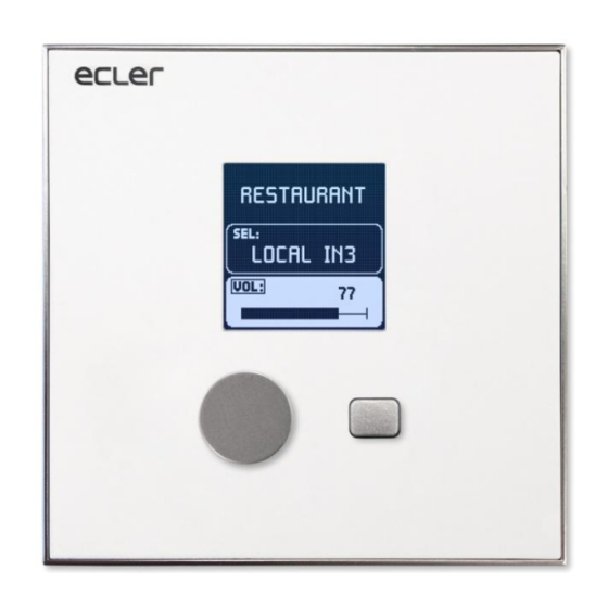
6. OPERATING THE UNIT 6.1 Controls eMCONTROL1 has 2 controls on its front panel: Rotating Encoder Selection key Figure 2: Front panel controls The main screen displays the label or name of the controlled zone, the source selection in that zone, and its volume control. Zone name Selected source Zone volume... -
Page 9: Equalization Screen
Using the selection key (short press), you can navigate between the source selection and the volume control. The editable option is displayed on a white background. On the other hand, the VOL or SEL indicator will be framed and blinking when this option is selected. ... -
Page 10: Information Messages
6.3 Information messages INFORMATION: press and hold the 2 control keys for a few seconds to access the information screen. It shows the name or label of eMCONTROL1 programmed using the HANGAR web application) and the firmware (it can be different from the name or label of the main screen area – it is version*. - Page 11 DISABLED CONTROL: displayed when trying to use a control (volume, source selection or equalization) that is disabled for that eMCONTROL1 panel. Figure 8: Disabled Control screen PANEL LOCKED: displayed when the temporary lock is activated for the user. To activate/deactivate this lock, press and hold selection key and rotary encoder for approx.
-
Page 12: Notes
outputs) is active (accessible from the HANGAR web application). PANIC ACTIVE: displayed when the PANIC button (the 16 muted audio Figure 11: Panic Active screen (PANIC button activated) 7. NOTES When connecting an eMCONTROL1 unit to an HUB matrix, the eMCONTROL1 unit will check whether its firmware needs to be updated, and if so, automatically performs update, without external manual intervention. -
Page 13: Front Panel
8. FRONT PANEL 1. Front panel faceplate 2. LCD screen 3. Selection button 4. Rotary encoder 9. BACK PANEL 1. External power supply connector 24VDC 2. Connector for WPaMIX-T interconnection 3. RJ-45 connector... -
Page 14: Block Diagram
10. BLOCK DIAGRAM 11. TECHNICAL SPECIFICATIONS Digital characteristics Control keys Encoder, SELECTION key Indicators LCD display – 128x128 pixels Communication standard RS485 Supply characteristics Nominal power supply From RJ45 remote input: 12VDC From External Input: 24VDC Minimum external power From RJ45 remote input without WPaMIX-T: 9.5V supply From RJ45 remote input with WPaMIX-T: 11V From External Input: 18VDC... -
Page 15: Mounting Drawings
12. MOUNTING DRAWINGS... -
Page 16: Package Contents
13. PACKAGE CONTENTS eMCONTROL1 Frame for mounting a mechanism in a system Screws for fixing to surface or flush mounting box Magnet for cover removal Surface mounting box Cable for direct connection to WPaMIX-T ... - Page 17 All product characteristics are subject to variation due to production tolerances. NEEC AUDIO BARCELONA S.L. reserves the right to make design or manufacturing changes that may affect these product specifications. Motors, 166‐168 08038 Barcelona ‐ Spain ‐ (+34) 932238403 information@ecler.es www.ecler.com...
Need help?
Do you have a question about the eMCTROL1 and is the answer not in the manual?
Questions and answers