Table of Contents
Advertisement
Quick Links
HFG01
Operation
Manual
Document number Y0321/DOC/038 Rev. 2
Author:
...............................................................
D Cullen BEng (Hons), MSc, CEng, CMgr, MIET, MIEEE, MCMI
Test Instrumentation Manager
Checked:
.....................................................................................
M S Anslow MEng, CEng, MIET MIEEE
Senior Engineer (Products)
Approved:
................................................................
D Cullen BEng (Hons), MSc, CEng, CMgr, MIET, MIEEE, MCMI
Test Instrumentation Manager
Products User Manual Template – Issue 2
Advertisement
Table of Contents

Summary of Contents for EMS HFG01
- Page 1 HFG01 Operation Manual Document number Y0321/DOC/038 Rev. 2 Author: ............... D Cullen BEng (Hons), MSc, CEng, CMgr, MIET, MIEEE, MCMI Test Instrumentation Manager Checked: ..................M S Anslow MEng, CEng, MIET MIEEE Senior Engineer (Products) Approved: ..............D Cullen BEng (Hons), MSc, CEng, CMgr, MIET, MIEEE, MCMI Test Instrumentation Manager Products User Manual Template –...
- Page 2 HFG01 Operation Manual HFG01 Operation Manual Document Number Y0321/DOC/038 HANGE ISTORY HEET Date Issue Pag/Para Description 30/03/2017 Issue 11/11/17 Safety instructions updated UNCONTROLLED ELECTRONIC COPY Users should satisfy themselves that they are in possession of the most up to date version of this manual by calling +44 (0) 330 4303456 or by emailing enquiry@yorkemc.com...
- Page 3 HFG01 Operation Manual Limited Warranty York EMC Services warrants each HFG01 to be free from defects in material and workmanship for a period of one year from the date of shipment to the purchaser. This warranty extends to the original purchaser only. It...
- Page 4 THAT MAY RESULT FROM THE USE OF THIS EQUIPMENT OUTSIDE ITS RECOMMENDED OPERATING CONDITIONS. PRECAUTIONS THE HFG01 MUST NOT BE OPERATED WITH THE TEST SUPPLY INPUT PLUGGED DIRECTLY INTO A PUBLIC MAINS SUPPLY SYSTEM. WHEN OPERATED, THE HFG01 WILL CAUSE HARMONIC AND FLICKER EMISSIONS TO THE SUPPLY CONNECTED TO THE TEST SUPPLY INPUT.
-
Page 5: Table Of Contents
HFG01 Operation Manual INTRODUCTION ....................6 DESCRIPTION ....................7 DESCRIPTION OF SYMBOLS ................8 SPECIFICATION ....................9 ..................9 PERATING MODES ......9 ARMONICS AND FLICKER MEASUREMENT SYSTEM TEST SUPPLY .................. 9 PERATOR INDICATORS .................. 9 OWER REQUIREMENTS ....................10 NCLOSURE ....................10... -
Page 6: Introduction
The HFG01 provides a series of harmonic and flicker disturbances of a nominal but stable level. The HFG01 may therefore be used to verify the stability of a measurement system. Additionally, due to its own stability it may be used as a transfer standard from a calibrated system, or be used as a repeatable source of interference for diagnostic and/or development design work. -
Page 7: Description
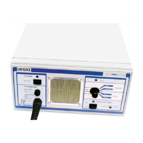
HFG01’s own supply needs from the Test Supply under test. For ease of access all connections, user controls, and indicators are located on the front panel of the HFG01. The HFG01 is supplied with the external power unit with mains cable, manufacturer’s test certificate, and a CDROM containing digital copies of the manual, test certificate, and files of the tabulated certificate data. -
Page 8: Description Of Symbols
HFG01 Operation Manual 3 DESCRIPTION OF SYMBOLS Symbols displayed on the product are listed below: Caution Protective Earth Terminal Alternating current HFG01 power supply on HFG01 power supply off Direct current DC connector polarity ESD handling precaution Separate collection for WEEE-... -
Page 9: Specification
Frequency 50 Hz Power rating 500 W max Connector CEE 7/7 European style plug for connecting the HFG01 to the Test Supply under test. Insulation rating 3000 Vrms 4.3 Operator indicators (See Section 4. Operation for a full description of the control and indicator functions) Operation indicators 4.3.1... -
Page 10: Enclosure
NOTE. Do not allow any obstructions to interfere with the operation of the fans, or site the HFG01 such that airflow is restricted. Doing so will cause the equipment to run at an increased temperature and in so doing may affect its operation. -
Page 11: Operation
A steady indicator warns of a system failure, which will need to be cleared by fully restarting the HFG01 (refer to Section 4.6). HFG01 power switch Main On/Off switch for the HFG01. -
Page 12: Supplying Power To The Hfg01
. Pressing the power switch with the 24 Vdc unit connected will turn the HFG01 on, which will be confirmed by the green indicator . Pressing the power switch again will turn the HFG01 off. -
Page 13: Enabling The Test
5.5 Performing a test. The HFG01 acts as the equipment under test in the harmonics and flicker test system, and should be connected to the single-phase test power supply as per the typical test setup used (Figure 5 for example). -
Page 14: Troubleshooting A Test
To do this, leave the HFG01 turned on but with no running test for approximately 10 to 15 minutes before fully powering down. - Page 15 HFG01 Operation Manual Figure 6: Troubleshooting flowchart ©York EMC Services Page 15 of 21 Doc. No. Y0321/DOC/038 Rev. 2...
-
Page 16: Output Performance
Typical performance results are shown in the sections below. 6.1 Flicker Load Operation The typical flicker disturbance generated by the HFG01 in each of the steady flicker modes when tested according to EN/IEC 61000-3-3 is shown in Table 3. Flicker Mode... -
Page 17: Calibration
The periodicity of these checks is typically determined by the quality assurance regime employed by the user, however it is recommended that the HFG01 output be retested annually. This service is available from York EMC Services and can be arranged through your supplier. -
Page 18: Safety
Do not wet the case of the HFG01 when cleaning it, for example by using a wet cloth or aerosol cleaning fluid. If the case has become wet through any circumstances then it MUST be dried before being connected to a power supply. -
Page 19: Electromagnetic Compatibility
These phenomena are deemed non applicable on the basis that the HFG01 has no relevant signal ports. The AC test port of the HFG01 may be looked upon as a signal port but the captive lead is less than 3m in length hence the tests do not apply. -
Page 20: Maintenance And Calibration
Ensure that the airflow through the fan and ventilation duct areas remains unobstructed, and that the HFG01 is in good condition. For all maintenance and calibration procedures, the HFG01 should be returned to York EMC Services for servicing by authorized personnel. - Page 21 HFG01 Operation Manual General Information Ordering Information Orders Standard Order Kits are listed for each product Orders are accepted with an accompanying in the YES Products Brochure. Please refer to Purchase Order Number. the appropriate part number when requesting a quote for a test instrument or accessory.
Need help?
Do you have a question about the HFG01 and is the answer not in the manual?
Questions and answers