
Related Manuals for Juniper C Series


Summary of Contents for Juniper C Series
- Page 1 C Series Controllers C2000 and C4000 Hardware Guide Release 3.2.x Juniper Networks, Inc. 1194 North Mathilda Avenue Sunnyvale, California 94089 408-745-2000 www.juniper.net Published: 2009-09-15...
- Page 2 Products made or sold by Juniper Networks or components thereof might be covered by one or more of the following patents that are owned by or licensed to Juniper Networks: U.S. Patent Nos. 5,473,599, 5,905,725, 5,909,440, 6,192,051, 6,333,650, 6,359,479, 6,406,312, 6,429,706, 6,459,579, 6,493,347, 6,538,518, 6,538,899, 6,552,918, 6,567,902, 6,578,186, and 6,590,785.
- Page 3 (g) distribute any key for the Software provided by Juniper to any third party; (h) use the Software in any manner that extends or is broader than the uses purchased by Customer from Juniper or an authorized Juniper reseller;...
- Page 4 (or services are accessed by) the Software shall be a third party beneficiary with respect to this Agreement, and such licensor or vendor shall have the right to enforce this Agreement in its own name as if it were Juniper. In addition, certain third party software may be provided with the Software and is subject to the accompanying license(s), if any, of its respective owner(s).
- Page 5 Software, whether oral or written (including any inconsistent terms contained in a purchase order), except that the terms of a separate written agreement executed by an authorized Juniper representative and Customer shall govern to the extent such terms are inconsistent or conflict with terms contained herein.
-
Page 7: Table Of Contents
CLI Management ..................6 SNMP MIB Management ................7 Part 2 Initial Installation Chapter 2 Unpacking and Inspecting the C Series Controller Before You Begin ...................11 Unpacking the Units ..................11 Inspecting System Components and Accessories ..........11 If You Detect or Suspect Damage ..............12 Contacting Juniper Networks .................12... - Page 8 C2000 and C4000 Hardware Guide Chapter 3 Installing and Cabling the C Series Controller Before You Begin ...................13 Freestanding Installation ................13 Rack-Mounted Installation ................14 Installation Guidelines ................14 Preparing the Equipment Racks ..............14 Installing the System ................14 Cabling the System ..................15 Cabling the Management Console ............15...
- Page 9 Managing Disks in a C Series Controller ............43 Replacing or Swapping a Disk ..............44 Reinitializing an Active Disk ..............44 Viewing Information About Disks on a C Series Controller ......45 Chapter 9 Configuring IPMI on a C Series Controller (SRC CLI) Overview of IPMI ..................47...
- Page 10 C2000 and C4000 Hardware Guide Power Cable Warning (Japanese) ............61 Working with Lasers ................61 VCCI Compliance ..................62 Safety Guidelines ...................62 Equipment Rack Requirements ..............63 Mechanical Requirements ...............63 Space Requirements ................64 Proper Rack Installation ................64 Cabling Recommendations ................64 Product Reclamation and Recycling Program ..........65 Hardware Compliance ...................66 Federal Communications Commission (FCC) Statement ......66 FCC Requirements for Consumer Products ..........66...
-
Page 11: About The Documentation
Requesting Technical Support on page xiv SRC Documentation and Release Notes For a list of related SRC documentation, see http://www.juniper.net/techpubs/ If the information in the latest SRC Release Notes differs from the information in the SRC guides, follow the SRC Release Notes. - Page 12 Represents examples in procedures. user@host# . . . Represents URLs. http://www.juniper.net/techpubs/software/ management/src/api-index.html Represents variables in SRC CLI commands. Italic sans serif typeface user@host# set local-address local-address Angle brackets In text descriptions, indicate optional Another runtime variable is <gfwif>.
- Page 13 (The keyword or variable may be either optional or required.) Obtaining Documentation To obtain the most current version of all Juniper Networks technical documents, see the products documentation page on the Juniper Networks Web site at http://www.juniper.net/ To download complete sets of technical documentation to create your own...
-
Page 14: Self-Help Online Tools And Resources
7 days a week, 365 days a year. Self-Help Online Tools and Resources For quick and easy problem resolution, Juniper Networks has designed an online self-service portal called the Customer Support Center (CSC) that provides you with the following features: Find CSC offerings: http://www.juniper.net/customers/support/... - Page 15 About the Documentation For international or direct-dial options in countries without toll-free numbers, see http://www.juniper.net/support/requesting support.html Requesting Technical Support...
- Page 16 C2000 and C4000 Hardware Guide Requesting Technical Support...
-
Page 17: Product Overview
Part 1 Product Overview C Series Controller Overview on page 3 Product Overview... - Page 18 C2000 and C4000 Hardware Guide Product Overview...
-
Page 19: Chapter 1 C Series Controller Overview
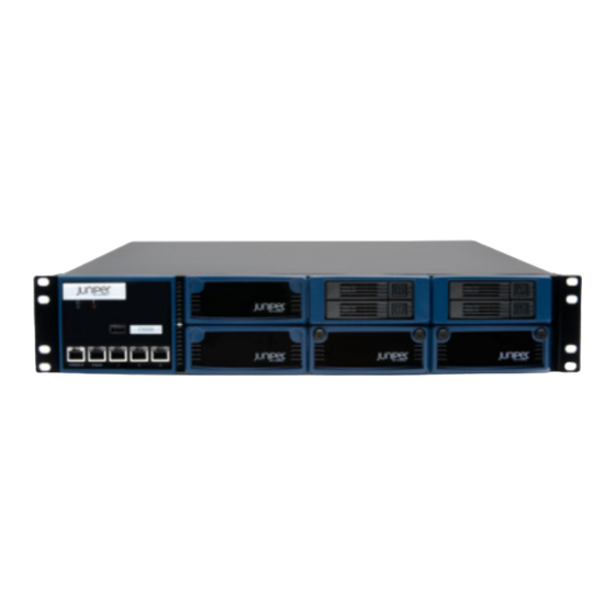
There are two C Series Controller models: the C2000 model and the C4000 model. Each model is composed of two hard drives, fans, redundant power supplies, two USB ports, a console management port, and four Ethernet ports. - Page 20 C2000 and C4000 Hardware Guide Table 3: C Series Model Differences (continued) Model Concurrent Subscribers C4000 500,000 NOTE: The models illustrated in this book might look different from your model because of configuration variations. Figure 1: C2000, Front View Figure 2: C2000, Rear View...
- Page 21 Chapter 1: C Series Controller Overview Figure 4: C4000, Rear View C Series Model Components The C2000 model and C4000 model contain the following components: Internal memory Hard drive Each model has two hot-swappable, redundant drives in a redundant array of independent disks (RAID) 1 (mirror) configuration. The C2000 model has two hard drives located in the front, and the C4000 model has two hard drives located in the rear.
-
Page 22: Cli Management
USB storage device Contains the latest system software, including the operating system for the C Series Controller. The device is read-only and should be used to recover from a major software failure. See the SRC Release Notes for more information about recovering from a software failure. -
Page 23: Snmp Mib Management
Chapter 1: C Series Controller Overview over any reachable network. For a full discussion of the CLI, see the SRC PE CLI User Guide. SNMP MIB Management The system offers a complete SNMP interface for configuration, status, and alarm reporting. For more information, see SRC PE Monitoring and Troubleshooting Guide. - Page 24 C2000 and C4000 Hardware Guide Network Management Tools...
- Page 25 Part 2 Initial Installation Unpacking and Inspecting the C Series Controller on page 11 Installing and Cabling the C Series Controller on page 13 Powering Up the C Series Controller on page 19 Setting the Initial Configuration on page 21...
- Page 26 C2000 and C4000 Hardware Guide Initial Installation...
-
Page 27: Unpacking And Inspecting The C Series Controller
Chapter 2 Unpacking and Inspecting the C Series Controller This chapter reviews shipping contents and unpacking procedures for the C Series Controller. Topics include: Before You Begin on page 11 Unpacking the Units on page 11 Inspecting System Components and Accessories on page 11... -
Page 28: If You Detect Or Suspect Damage
Contact your Juniper Networks sales representative or reseller. Contacting Juniper Networks Please contact Juniper Networks at 1-888-314-JTAC (from the United States, Canada, or Mexico) or 1-408-745-9500 (from elsewhere), or contact your sales representative if you have any questions or concerns. See “Contacting Customer Support and Returning Hardware”... -
Page 29: Installing And Cabling The C Series Controller
Chapter 3 Installing and Cabling the C Series Controller This chapter describes how to install the C Series Controller and attach cables. Topics include: Before You Begin on page 13 Freestanding Installation on page 13 Rack-Mounted Installation on page 14... -
Page 30: Installation Guidelines
C2000 and C4000 Hardware Guide WARNING: Two people are required to lift the system. CAUTION: To prevent electrostatic damage to the system and its components, make sure persons handling the system wear an antistatic device. Rack-Mounted Installation We recommend that you use a standard EIA distribution rack. See “Equipment Rack Requirements”... -
Page 31: Cabling The System
Chapter 3: Installing and Cabling the C Series Controller Starting at the bottom of the system, have the third person secure the system in the equipment rack by using the 10-32 x 3/8 Phillips screws. Connect the necessary cables. Cabling the System... -
Page 32: Cabling Ethernet Interfaces
C2000 and C4000 Hardware Guide See “Setting the Initial Configuration” on page 21 for more information about management access. Connecting to the Network To connect the system to the network: Insert an Ethernet cable (RJ-45) connector into the 10/100Base-T (RJ-45) port on the system until it clicks into place. -
Page 33: The Next Step
Figure 7: C2000, Front View Figure 8: C2000, Rear View Figure 9: C4000, Front View Figure 10: C4000, Rear View The Next Step After you finish installing and cabling the system: See “Powering Up the C Series Controller” on page 19. The Next Step... - Page 34 C2000 and C4000 Hardware Guide The Next Step...
-
Page 35: Powering Up The C Series Controller
Chapter 4 Powering Up the C Series Controller This chapter describes how to power up the C Series Controller. Topics include: Powering Up on page 19 Status LEDs on page 20 The Next Step on page 20 Powering Up NOTE: In this procedure we assume that the system is already connected to a power source. -
Page 36: The Next Step
C2000 and C4000 Hardware Guide Status LEDs The LEDs listed in Table 4 on page 20 are used on both models. Table 4: Model LEDs LED Label LED Indicator LED Color OFF to ON ON to OFF Power Green Power on Power off Hard drive Hard drive is... -
Page 37: Setting The Initial Configuration
Chapter 5 Setting the Initial Configuration This chapter discusses how to set up the C Series Controller after powering it on. For basic information on the management of the system, see the SRC PE Getting Started Guide. Topics include: Configuration Overview on page 21... - Page 38 SRC data, sample data, configuration information, and user profiles. You must enable the Juniper Networks database the first time you power on the system. It can operate as a standalone database or as a member of a community of Juniper Networks databases.
- Page 39 In community mode, databases distribute data changes among specified databases. When you have two or more C Series Controllers, enable the Juniper Networks database to run in community mode, and assign a role to each database: Primary role A database that provides read and write access to client applications.
- Page 40 You can specify an IP address with mask or a broadcast address with mask for an interface. For more information, see SRC PE Getting Started Guide, Chapter 7, Configuring Remote Access to a C Series Controller. To configure the generic interfaces: From configuration mode, access the configuration statement that configures the interface.
- Page 41 Telnet connection. For more information, see SRC PE Getting Started Guide, Chapter 7, Configuring Remote Access to a C Series Controller with the SRC CLI. To configure the system to accept SSH connections: From configuration mode, access the [edit system services ssh] hierarchy level.
- Page 42 C2000 and C4000 Hardware Guide admin account to allow further configuration. You can use a built-in class, such as super-user. To configure an account for an administrative user: Create an account for an administrative user. [edit] user@host # edit system login user user For example: [edit] user@host # edit system login user myadmin...
-
Page 43: The Next Step
Chapter 5: Setting the Initial Configuration The Next Step See “Maintaining the System” on page 31. The Next Step... - Page 44 C2000 and C4000 Hardware Guide The Next Step...
- Page 45 System Specifications on page 39 Managing RAID Disks on a C Series Controller on page 43 Configuring IPMI on a C Series Controller (SRC CLI) on page 47 Configuring IPMI on a C Series Controller (C-Web Interface) on page 55...
- Page 46 C2000 and C4000 Hardware Guide Hardware Maintenance Procedures and Specifications...
-
Page 47: Maintaining The System
This chapter lists the tools, items, and steps needed for installing and uninstalling components. Other maintenance procedures must be performed by an authorized Juniper Networks technician. Topics include: Required Tools and Items on page 31 Storing Modules and Components on page 31... - Page 48 C2000 and C4000 Hardware Guide Store each component in a separate antistatic bag. Store components in an antistatic plastic container. Some of these containers can accommodate several components in separate compartments. Do not store multiple components in an antistatic bag or container where they can touch other items.
-
Page 49: Tools And Parts Required
Chapter 6: Maintaining the System Figure 12: C4000, Front View Tools and Parts Required To remove and replace an SFP, you need the following tools and parts: Electrostatic bag or antistatic mat, one for each SFP removed ESD grounding wrist strap Rubber safety caps to cover each unused cable and SFP Removing an SFP To remove an SFP:... -
Page 50: Installing An Sfp
C2000 and C4000 Hardware Guide CAUTION: Make sure that you open the ejector handle completely (you will hear it click). This prevents damage to the SFP. Grasp the SFP ejector handle, and pull the SFP approximately 0.5 in (1.3 cm) out of the interface port. -
Page 51: Removing And Installing A Fan
Chapter 6: Maintaining the System Removing and Installing a Fan Both C Series models have two cooling fans that provide forced air cooling for components in the system. Each fan is hot-swappable; you can replace it without powering down the system. You can monitor fan status by observing the TEMP LED. -
Page 52: Removing And Installing A Hard Drive
C2000 and C4000 Hardware Guide Unplug the power cord. Slide the locking tab (ejector button) to the left to release the module. See Figure 14 on page 36 and Figure 15 on page 36. Hold the tab to the left, and using the handle, slowly pull the power supply module out. - Page 53 Chapter 6: Maintaining the System To install a hard drive, hold the locking tab to the right and slowly slide the unit into the chassis until it clicks into place. Removing and Installing a Hard Drive...
- Page 54 C2000 and C4000 Hardware Guide Removing and Installing a Hard Drive...
-
Page 55: Chapter 7 System Specifications
Chapter 7 System Specifications This chapter lists the system specifications, requirements, and certifications for the system. Topics include: C2000 Model Specifications on page 39 C4000 Model Specifications on page 40 C2000 Model Specifications Table 5: C2000 Model Specifications Category Specification 33 lb (15 kg) Weight 3.5 (H) x 16.7 (W) x 16.2 (D) inches... - Page 56 C2000 and C4000 Hardware Guide Table 5: C2000 Model Specifications (continued) Category Specification Efficiency 70% minimum at full load 3 feet (90 cm) behind system or rack. Space Requirements Do not block air vents on front or back of the system. CAN/CSA-C22.2 No.
- Page 57 Chapter 7: System Specifications Table 6: C4000 Model Specifications (continued) Category Specification Ambient storage humidity 5% to 95% (noncondensing) 700 W, 2389 BTU/hour maximum Heat Dissipation AC Input Power required 90-264 VAC, 47–63 Hz Power 700 W Efficiency 80% minimum at full load 3 feet (90 cm) behind system or rack.
- Page 58 C2000 and C4000 Hardware Guide C4000 Model Specifications...
-
Page 59: Chapter 8 Managing Raid Disks On A C Series Controller
RAID controller copies all the data from the active disk to the enabled or initialized disk and establishes mirroring for the two disks. The location of the disk mount for the disks depends on the model of the C Series Controller:... -
Page 60: Replacing Or Swapping A Disk
C2000 and C4000 Hardware Guide Replacing or Swapping a Disk You can replace a failed disk or swap a working disk in a C Series Controller. Note the following limitations: Replacing a disk You can replace it while the other disk remains active. -
Page 61: Viewing Information About Disks On A C Series Controller
Chapter 8: Managing RAID Disks on a C Series Controller Viewing Information About Disks on a C Series Controller To view information about disks in the C Series Controller: Enter the command. show disk status user@host> show disk status ----------------------------------------------------------------------... - Page 62 Device is an Enclosure Type : SAF-TE Vendor : QLogic Model : GEM424 Firmware : 0101 Status of Enclosure Temperature status : Normal Command completed successfully. Current operation : None Command completed successfully. Managing Disks in a C Series Controller...
-
Page 63: Configuring Ipmi On A C Series Controller (Src Cli)
Chapter 9 Configuring IPMI on a C Series Controller (SRC CLI) This chapter describes how to configure IPMI on a C Series Controller with the SRC CLI. Topics include: Overview of IPMI on page 47 Commands to Manage an IPMI Interface on page 48... - Page 64 C2000 and C4000 Hardware Guide Commands to Manage an IPMI Interface You can use the following operational mode commands to manage IPMI interfaces: ipmisol open ipmisol close remote-session ipmisol close local-session For detailed information about each command, see the SRC PE CLI Command Reference.
- Page 65 Chapter 9: Configuring IPMI on a C Series Controller (SRC CLI) address 10.227.7.145/24; gateway 10.227.7.1; Viewing IPMI Chassis Information You can view IPMI chassis information for the controller you are currently logged in to and for a remote controller. You must be logged on as a root user.
- Page 66 Enter the password. Password: password You are now logged in as root user. Access the CLI. [root@host ~]# cli --- SRC CLI 3.1 build CLI.R.3.1.0.012 (c) 2005-2008 Juniper Networks Inc. root@host> Enter the command. show ipmi power For example: root@host>show ipmi power...
- Page 67 Powering a Controller On and Off Using IPMI You can power on or off, and reset a C Series Controller you are currently logged in to and for a remote controller. You must be logged on as a root user.
- Page 68 C2000 and C4000 Hardware Guide reset Perform a hard reset on a C Series Controller. cycle Power off and then power on a C Series Controller. For example: user@host>request ipmi power off To execute a power command on a remote controller using IPMI: Log in as root user.
- Page 69 Connecting to a Serial Console Using IPMI Serial over LAN (SOL) IPMI SOL enables a remote user to monitor and manage a C Series Controller through a serial console by means of an IPMI session. IPMI SOL redirects the C Series Controller's serial port input and output over IP.
- Page 70 C2000 and C4000 Hardware Guide To disconnect from a local host using IPMI SOL: From operational mode, enter the command to close ipmisol close local-session the active IPMI connection to a local host. user@host>ipmisol close local-session host To disconnect from a remote host using IPMI SOL: From operational mode, enter the command to ipmisol close remote-session...
-
Page 71: Configuring Ipmi On A C Series Controller (C-Web Interface)
Chapter 10 Configuring IPMI on a C Series Controller (C-Web Interface) This chapter describes how to configure IPMI on a C Series Controller with the C-Web interface. Topics include: Overview of IPMI on page 55 Configuring IPMI with the C-Web Interface on page 55... - Page 72 C2000 and C4000 Hardware Guide Click Configure, expand System, and then click IPMI. The IPMI pane appears. In the Address box, enter an IP address. An IP address is required for a C2000 model but is set automatically to the address of the eth0 interface on a C4000 model.
- Page 73 Chapter 10: Configuring IPMI on a C Series Controller (C-Web Interface) Deleting an IPMI User Account with the C-Web Interface To delete an IPMI user account: Click Configure, expand System, and then click IPMI. In the side pane under IPMI, select the user account you want to delete.
- Page 74 C2000 and C4000 Hardware Guide Renaming an IPMI User Account with the C-Web Interface...
-
Page 75: Installation Guidelines And Requirements
Chapter 11 Installation Guidelines and Requirements This chapter reviews preinstallation considerations such as electrical, environmental, and safety compliances for the C Series Controllers. For complete system specifications, see “System Specifications” on page 39. Topics include: Your Preinstallation Responsibilities on page 59... -
Page 76: Regulatory Compliances
C2000 and C4000 Hardware Guide Choose a location for the system that is dry, relatively dust free, well ventilated, and air conditioned. If you install equipment in a rack, be sure that the floor is capable of supporting the combined weight of the rack and the installed equipment. Place the system in a location with sufficient access to power and network cables. -
Page 77: Power Cable Warning
WARNING: The attached power cable is only for this product. Do not use the cable for another product. Working with Lasers Some Juniper Networks devices are equipped with fiber-optic ports, which emit radiation that may be harmful to the human eye. Fiber-optic ports are considered Class 1 laser or Class 1 LED ports. -
Page 78: Vcci Compliance
C2000 and C4000 Hardware Guide WARNING: Class 1 LED product. WARNING: Do not stare into the laser beam or view it directly with optical instruments. To avoid exposure to radiation, do not stare into the aperture of a fiber-optic port. Invisible radiation might be emitted from the aperture of the port when no fiber cable is connected. -
Page 79: Equipment Rack Requirements
Chapter 11: Installation Guidelines and Requirements WARNING: Three people are required to install the system in a rack: two to lift the system into position and one to screw it to the rack. WARNING: Connect the system or rack to ground (earth), and ensure that a reliable grounding path is maintained in the rack. -
Page 80: Space Requirements
±.063 inch, as specified in EIA-310-D. An optional mounting kit is available for midchassis mounting. Contact your Juniper Networks sales representative for more information. Space Requirements If you use an enclosed rack for the system, ensure that there is a minimum of 3 inches of clearance between the inner side wall and the system. -
Page 81: Product Reclamation And Recycling Program
Equipment Building System (NEBS) Requirements: Physical Protection, Issue 2, April 2002. Product Reclamation and Recycling Program Juniper Networks is committed to environmentally responsible behavior. As part of this commitment, we continually work to comply with environmental standards such as the European Union’s Waste Electrical and Electronic Equipment (WEEE) Directive and Restriction of Hazardous Substances (RoHS) Directive. -
Page 82: Hardware Compliance
C2000 and C4000 Hardware Guide Hardware Compliance C Series Controllers meet the hardware compliance requirements in this topic. Federal Communications Commission (FCC) Statement This equipment has been tested and found to comply with the limits for a Class A digital device, pursuant to Part 15 of the FCC Rules. These limits are designed to provide reasonable protection against harmful interference when the equipment is operated in a commercial environment. -
Page 83: Canadian Department Of Communications Radio Interference Regulations
Chapter 11: Installation Guidelines and Requirements Canadian Department of Communications Radio Interference Regulations This Class B (or Class A, if so indicated on the registration label) digital apparatus meets the requirements of the Canadian Interference-Causing Equipment Regulations. Réglement sur le brouillage radioélectrique du ministère des communications Cet appareil numérique de la Classe B (ou Classe A, si ainsi indiqué... -
Page 84: D.o.c. Explanatory Notes: Equipment Attachment Limitations
C2000 and C4000 Hardware Guide Les réparations de l'appareillage certifié devraient être confiées à un service d'entretien canadien désigné par lefournisseur. En cas de réparation ou de modification effectuées par l'utilisateur ou de mauvais fonctionnement del'appareillage, le service de télécommunications peut demander le débranchment de l'appareillage. -
Page 85: Notes Explicatives Du Ministère Des Communications: Limites Visant Les Accessoires
Chapter 11: Installation Guidelines and Requirements Notes explicatives du ministère des Communications: limites visant les accessoires L'étiquette du ministère des Communications du Canada indique que l'appareillage est certifié, c'est-à-dire qu'il respecte certaines exigences de sécurité et de fonctionnement visant les réseaux de télécommunications. Le ministère ne garantit pas que l'appareillage fonctionnera à... - Page 86 C2000 and C4000 Hardware Guide Hardware Compliance...
-
Page 87: Contacting Customer Support And Returning Hardware
Chapter 12 Contacting Customer Support and Returning Hardware See the Juniper Networks Web site for complete customer service information: http://www.juniper.net/support/guidelines.html Topics in this chapter include: Contacting Customer Support on page 71 Return Procedure on page 71 Locating Component Serial Numbers on page 72... - Page 88 “Returning Products for Repair or Replacement” on page 73. Locating Component Serial Numbers Before contacting Juniper Networks to request a RMA, you must find the serial number on the chassis or component. To list all the chassis components and their serial numbers, enter the following command: user@host>show system information...
-
Page 89: Packing Instructions For Returning A Chassis
Wire cutters Returning Products for Repair or Replacement In the event of a hardware failure, please contact Juniper Networks to obtain a Return Material Authorization (RMA) number. This number is necessary to ensure proper tracking and handling of returned material at the factory. Do not return any hardware until you have received an RMA. - Page 90 C2000 and C4000 Hardware Guide Returning Products for Repair or Replacement...
-
Page 91: Declaration Of Conformity
Declaration of Conformity – C2000 Controller on page 75 Declaration of Conformity – C4000 Controller on page 76 Declaration of Conformity C2000 Controller Declaration of Conformity Juniper Networks, Inc. 10 Technology Park Drive Westford, Massachusetts 01886 USA declares that under our sole responsibility the product(s) Server... - Page 92 C2000 and C4000 Hardware Guide Declaration of Conformity C4000 Controller Declaration of Conformity Juniper Networks, Inc. 10 Technology Park Drive Westford, Massachusetts 01886 USA declares that under our sole responsibility the product(s) Server Model C4000 is in conformity with the provisions of the following EC Directives, including all amendments,...
-
Page 93: Part 4 Index
Part 4 Index Index on page 79 Index... - Page 94 C2000 and C4000 Hardware Guide Index...
- Page 95 21 airflow................59 rack-mounted installation and......14 EIA distribution rack............14 antistatic bags and containers........31 electronic equipment, recycling........65 assembly numbers, locating.........72 environmental requirements........59 Ethernet interfaces............6 C Series Controllers cabling recommendations........64 cleaning..............32 failure..............35 environmental requirements........59 hot-swapping............35 equipment rack requirements.......63 removing..............35 safety guidelines...........62 space requirements..........64...
- Page 96 73 tools required, removing components....31, 73 troubleshooting network management..........6, 21 safety guidelines...........62 notice icons..............xi unpacking C Series Controller........11 packaging, recycling.............65 USB port................6 packing instructions.............73 USB storage device............6 preinstallation responsibilities........59 product numbers, locating...........72 ventilation..............14 rack, distribution............14...
Need help?
Do you have a question about the C Series and is the answer not in the manual?
Questions and answers