
Related Manuals for Pulsar PSBEN 2024B/LCD


Summary of Contents for Pulsar PSBEN 2024B/LCD
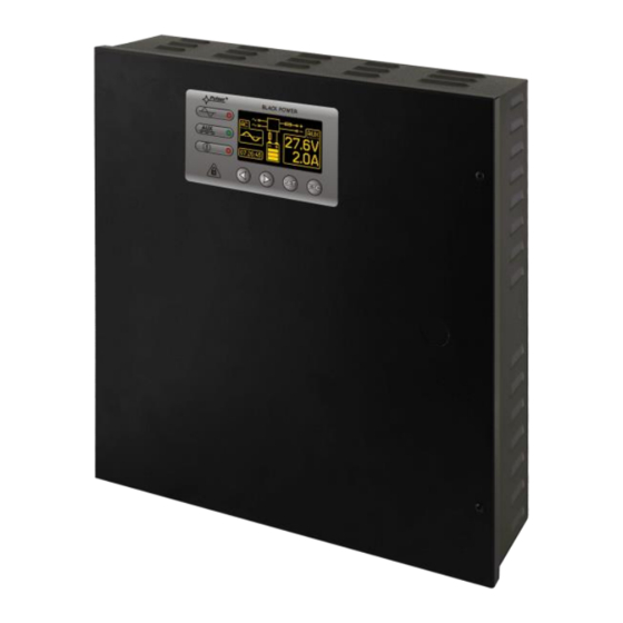
- Page 1 PSBEN 2024B/LCD v.1.0 PSBEN 27,6V/2A/2x7Ah/EN/LCD Buffer, switched mode power supply unit. Edition: 3 from 20.11.2012 Supersedes the: 2 from 14.09. 2012 edition...
-
Page 2: Table Of Contents
PSBEN2024B/LCD CONTENTS 1. FUNCTIONAL REQUIREMENTS OF THE PSU COMPLIANT WITH PN-EN 50131-6.... 4 2. TECHNICAL DESCRIPTION........................5 2.1. G ................................5 ENERAL DESCRIPTION 2.2. B ..................................5 LOCK DIAGRAM 2.3 D PSU’ ......................6 ESCRIPTION OF S COMPONENTS AND CONNECTORS 3. OPERATING STATUS INDICATION....................7 3.1. - Page 3 PSBEN2024B/LCD 7. INSTALLATION............................29 7.1 R ..................................29 EQUIREMENTS 7.2 I ............................... 29 NSTALLATION PROCEDURE 8. OPERATION AND USE........................... 30 8.1. O ....................... 30 VER VOLTAGE PROTECTION AT THE OUTPUT 8.2 O PSU................................30 VERLOAD OF THE 8.3 S...
-
Page 4: Functional Requirements Of The Psu Compliant With Pn-En 50131-6
PSBEN2024B/LCD Features: • • PN-EN50131-6 compliance, grades 1÷3 and II remote test of the PSU (additional module required) • environmental class START button for battery activation • • mains supply of 230VAC STOP button for disconnecting during battery-assisted •... -
Page 5: Technical Description
PSBEN2024B/LCD 2. Technical description. 2.1. General description. The buffer power supply has been designed in accordance with the requirements of the PN-EN 50131-6 standard, grade 1÷3 and II environmental class. It is intended for an uninterrupted supply to alarm system devices requiring stabilized voltage of 24V/DC (+/-15%). -
Page 6: Description Of Psu's Components And Connectors
PSBEN2024B/LCD 2.3 Description of PSU’s components and connectors. Table 1. Elements of the PSU pcb (see Fig. 2). Element no. Description PANEL – optical indication connector – jumper; idle in this model – jumpers J1, J2; idle in this model CAUTION. -
Page 7: Operating Status Indication
PSBEN2024B/LCD Table 2. PSU elements (see fig. 3). Element no. Description Insolation transformer PSU board (tab.1, fig.2) TAMPER; micro-switch (contacts) of tamper resistance (NC) fuse in the supply circuit (230 V AC) MAIN L-N 230V/AC power connector, PE connector... -
Page 8: Main Screen Of The Lcd Display
PSBEN2024B/LCD Table 3. A description of buttons and LEDs of the LCD panel. - move the cursor on the display - selection approval - leaving the editing mode without changing the values - entering the overview menu mode - red LED indicating the presence of AC voltage... -
Page 9: Information Displayed On The Panel
PSBEN2024B/LCD 3.3 Information displayed on the panel. 3.3.1. Overview menu. After pressing the ‘ESC’ button, an overview menu appears at the bottom of the display. It enables choosing one of three available PSU screens: - parameters of the PSU - history of the PSU’s parameters... -
Page 10: Screen - History Of The Psu's Parameters
PSBEN2024B/LCD PSU technical outputs’ status: EPS – AC network presence indication open = AC power failure close = AC power - O.K. PSU – PSU failure indication open = failure close = PSU working correctly - O.K. APS – battery failure indication... -
Page 11: Psu Settings
PSBEN2024B/LCD Fig. 9. Failure history screen. In chapter 9, there have been listed codes of all possible failures that may occur during the PSU operation. Each code is accompanied by appropriate optical indication on the panel, acoustic indication and activation of a dedicated technical output. -
Page 12: Entering The Password
PSBEN2024B/LCD Entering the password. - set menu with ‘>’ or ‘<’ Password (enter/change) - press the ‘SET’ button, another window with available levels of passwords will appear - with ‘>’ or ‘<’ choose the right level of the password - confirm your choice with the ‘SET’... -
Page 13: Password Change
PSBEN2024B/LCD If the typed password is incorrect, the following message will appear: Fig. 11. The message after entering a wrong keypad password. If none of the buttons is pressed within the next 30 seconds, the PSU settings will be locked automatically. -
Page 14: Psu
PSBEN2024B/LCD 3.4.2 PSU. The facility is only available after entering the correct installer’s password. Selecting the “PSU” entry in the setting menu enables entering another menu from which the full PSU’s settings configuration is possible. After entering the right settings, they are stored in non-volatile memo which protects the PSU against data loss in case of a failure of mains power decay. -
Page 15: Setting The Battery Test
PSBEN2024B/LCD - with ‘>’ or ‘<’ set ‘YES’ or ‘NO’ – if the battery is connected to the PSU – if the battery is not connected to the PSU - confirm your choice with the ‘SET’ button Setting the battery test. -
Page 16: Setting The Eps Output Lag
PSBEN2024B/LCD - press the ”SET” button, you will see the prompt at the end of the line - with ‘>’ or ‘<’ set ‘YES’ or ‘NO’ – battery protection function (disconnection) on – battery protection function (disconnection) off - confirm your choice with the ‘SET’ button Setting the EPS output lag. -
Page 17: Setting The Communication Address
PSBEN2024B/LCD Setting the communication address. - with ‘>’ or ‘<’ choose the Communication address menu - press the ”SET” button, you will see the prompt at the end of the line - change the setting with ‘>’ or ‘<’... -
Page 18: Setting The Language Of Messages
PSBEN2024B/LCD Setting the language of messages. - with ‘>’ or ‘<’ choose the Language menu - press the ”SET” button, you will see the prompt at the end of the line - with ‘>’ or ‘<’ choose the language of messages - confirm your choice with the ‘SET’... -
Page 19: Setting The Time
PSBEN2024B/LCD - with ‘>’ or ‘<’ set the current month - press the ‘SET’ button, the prompt will move to the day section - with ‘>’ or ‘<’ set the current day - approve the settings with the ‘SET’ button Setting the time. -
Page 20: Setting The Contrast
PSBEN2024B/LCD - with ‘>’ or ‘<’ choose the Highlight. menu (abbr. Highlighting) - press the ‘SET’ button, the prompt will appear next to the constant< option - with ‘>’ or ‘<’ change the setting into 60 s - press the ‘SET’ button, the prompt will move to the end of the line - with ‘>’... -
Page 21: Acoustic Indication
PSBEN2024B/LCD - with ‘>’ or ‘<’ set the contrast - approve your choice with the ‘SET’ button 3.5 Acoustic indication. Emergency situations are acoustically indicated. The frequency and the number of signals depend on an event type (see chapter 9). The acoustic indication is off after removing an appropriate jumper (fig. 2, [5]). -
Page 22: Input Of Collective Failure: Ext In
PSBEN2024B/LCD Fig. 15. Electrical diagram of the technical outputs. • TAMPER - output that indicates tampering with the PSU enclosure: output with volt-free (potential- free) contacts indicating the door status and PSU detachment from the mounting surface. NC contacts: the PSU is locked and fixed to the dedicated surface. -
Page 23: Battery-Assisted Operation
PSBEN2024B/LCD 4. Battery-assisted operation. 4.1. Running the PSU from the battery. The PSU has been equipped with two buttons on the pcb board which enable running or disconnecting the PSU during battery-assisted operation. • Running the PSU from the battery: press the START button on the main board and hold for 1s. -
Page 24: Battery Charging Time
PSBEN2024B/LCD 4.5. Battery charging time. The PSU has a battery circuit charged with direct current. The current selection is done via I jumpers. The table below shows how long it takes to charge a (fully discharged) battery up to min. 80% of its nominal capacity. -
Page 25: Remote Monitoring (Option: Wi-Fi, Ethernet, Rs485, Usb)
PSBEN2024B/LCD 5. Remote monitoring (option: Wi-Fi, Ethernet, RS485, USB). The PSU has been adjusted to operate in a system that requires a remote control of the parameters in a monitoring centre. Transmitting data concerning PSU status is possible due to an additional, external communication module that is responsible for communication in Wi-Fi, Ethernet or RS485 standard. -
Page 26: Usb-Ttl Communication
PSBEN2024B/LCD Fig. 21. RS485 communication with the use of the interfaces: ”INTR” and ”INTUR”. 5.4 USB-TTL communication. If the PSU does not cooperate with any of previously mentioned network and the access to the parameters’ adjustment and memo readings are necessary, the USB-TTL ”INTU” needs to be used. This interface allows direct connection between the computer and the PSU and it is recognisable by the operating system as a virtual COM port. -
Page 27: Technical Specifications
PSBEN2024B/LCD The main panel of the program has been formulated in such a way that it is possible to divide it into smaller areas, depending on the number of power supplies. The program enables both a visualisation and an analysis of the received data. Exceeding of the acceptable parameters is indicated by highlighting in red the appropriate area or by twinkling of the indicator. -
Page 28: Psu' S Factory Settings
PSBEN2024B/LCD Voltage ’on’ – 10 ÷ 30V DC EXT IN technical input Voltage ’off’ – 0 ÷ 2V DC Level of galvanic isolation: 1500V - LEDs on the PSU’s pcb, - LCD panel • electrical parameters reading • failure indication •... - Page 29 PSBEN2024B/LCD 7. Installation. 7.1 Requirements. The buffer PSU is to be mounted by a qualified installer, holding relevant permits and licenses (applicable and required for a given country) for 230V/AC interference and low-voltage installations. The unit should be mounted in confined spaces, in accordance with the II environmental class, with normal relative humidity (RH=90% maximum, without condensation) and temperature from -10°...
- Page 30 PSBEN2024B/LCD 8. Check the output voltage (the PSU voltage without load and without a battery should amount to 27,5 V ÷ 27,7 V, with a battery or during battery charging process: 22 V÷27,6 V). If the value of the voltage requires adjustment, it should be set by the V potentiometer, monitoring the voltage at the AUX output of the PSU.
- Page 31 PSBEN2024B/LCD 9. PSU FAILURE CODES. Failure LED indication Technical Acoustic Fault description Causes code outputs indication activation EPS FLT - No AC mains Battery-assisted 1 beep supply operation per 10s - Faulty main fuse MAIN PSU FLT PTC polyswitch...
- Page 32 GENERAL WARRANTY CONDITIONS 1. Pulsar K. Bogusz Sp.j. (the manufacturer) grants a five-year warranty for the equipment, counted from the device’s production date. 2. The warranty includes free-of-charge repair or replacement with an appropriate equivalent (the selection is at the manufacturer’s discretion) if the malfunction is due to the manufacturer, includes manufacturing or material defects, unless such...
Need help?
Do you have a question about the PSBEN 2024B/LCD and is the answer not in the manual?
Questions and answers