
Related Manuals for Pulsar BLACK POWER PSBEN 2024B


Summary of Contents for Pulsar BLACK POWER PSBEN 2024B
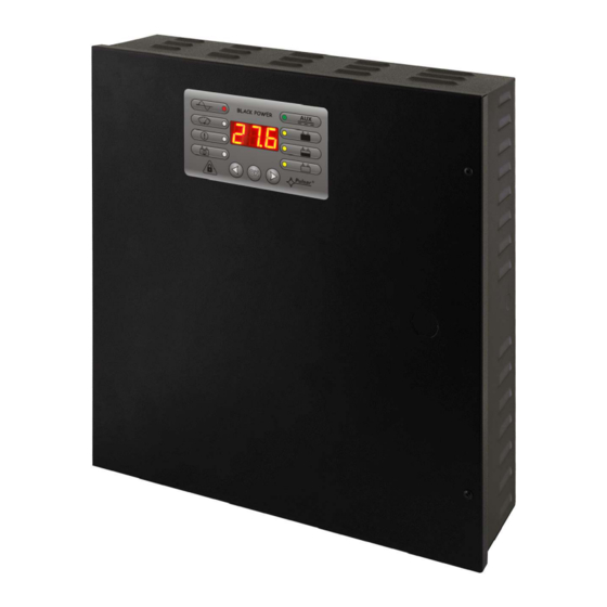
- Page 1 PSBEN 2024B v.1.0 PSBEN 27,6V/2A/2x7Ah/EN Buffer, switched mode power supply unit. Edition: 3 from 20.11.2012 Supersedes the: 2 from 14.09.2012 edition...
-
Page 2: Table Of Contents
PSBEN2024B CONTENTS 1. FUNCTIONAL REQUIREMENTS OF THE PSU COMPLIANT WITH PN-EN 50131-6.... 3 2. TECHNICAL DESCRIPTION........................4 2.1. G ................................4 ENERAL DESCRIPTION 2.2. B ..................................4 LOCK DIAGRAM 2.3 D PSU’ ......................5 ESCRIPTION OF S COMPONENTS AND CONNECTORS 3. OPERATING STATUS INDICATION....................7 3.1. -
Page 3: Functional Requirements Of The Psu Compliant With Pn-En 50131-6
PSBEN2024B Features: • PN-EN50131-6 compliance, grades 1÷3 and II • remote test of the PSU (additional module required) • START button for battery activation environmental class • mains supply of 230VAC • STOP button for disconnecting during battery-assisted • uninterrupted voltage of 27,6VDC operation •... -
Page 4: Technical Description
PSBEN2024B 2. Technical description. 2.1. General description. The buffer power supply has been designed in accordance with the requirements of the PN-EN 50131-6 standard, grade 1÷3 and II environmental class. It is intended for an uninterrupted supply to alarm system devices requiring stabilized voltage of 24V/DC (+/-15%). -
Page 5: Description Of Psu's Components And Connectors
PSBEN2024B 2.3 Description of PSU’s components and connectors. Table 1. Elements of the PSU pcb (see Fig. 2). Element no. Description PANEL – optical indication connector ; pin - adjustment of battery protection function UVP • battery protection (disconnection) off •... - Page 6 PSBEN2024B Fig. 2. The view of the PSU’s pcb. Table 2. PSU elements (see fig. 3). Element no. Description Insolation transformer PSU board (tab.1, fig.2) TAMPER; micro-switch (contacts) of tamper resistance (NC) fuse in the supply circuit (230 V AC)
-
Page 7: Operating Status Indication
PSBEN2024B 3. Operating status indication. 3.1. Control panel. The PSU is equipped with a panel with buttons and an LED display which enables reading the basic parameters of the device. The buttons are for selecting and approving a certain parameter that is to be displayed. -
Page 8: Overview Of Current Failures
PSBEN2024B Fig. 5. Menu of the display. • - PSU fault memo (30 last events) • - AUX output current measurement [A] • - AUX output voltage measurement [V] Resolution for voltage measurement amounts to 0.1V, for current measurement: 0.1A. Displayed voltage and current rates are only approximate. -
Page 9: Technical Outputs
PSBEN2024B 3.5 Technical outputs. The PSU feature indication outputs, with galvanic isolation, which change state if any of the following event occur: • EPS FLT – output indicating AC power loss. The output indicates AC power loss. Under normal status – with the 230V AC supply, the output is close. -
Page 10: Battery-Assisted Operation
PSBEN2024B The electrical diagram below shows the way of connecting external devices to the EXT IN input. Outputs such as: OC (open collector), relay type or tamper may be used as a source of the signal. Fig. 8. Examples of connections. -
Page 11: Dynamic Battery Test
PSBEN2024B 4.3 Dynamic battery test. The PSU runs a battery test every 10 minutes. It is done by a momentary switching into a battery-assisted operation. A failure is indicated when voltage drops below 24V. The battery test facility can be switched off. -
Page 12: Remote Monitoring (Option: Wi-Fi, Ethernet, Rs485, Usb)
PSBEN2024B 5. Remote monitoring (option: Wi-Fi, Ethernet, RS485, USB). The PSU has been adjusted to operate in a system that requires a remote control of the parameters in a monitoring centre. Transmitting data concerning PSU status is possible due to an additional, external communication module that is responsible for communication in Wi-Fi, Ethernet or RS485 standard. -
Page 13: Usb-Ttl Communication
PSBEN2024B Fig. 12. RS485 communication with the use of the interfaces: ”INTR” and ”INTUR”. 5.4 USB-TTL communication. If the PSU does not cooperate with any of previously mentioned network and the access to the parameters’ adjustment and memo readings are necessary, the USB-TTL ”INTU” needs to be used. This interface allows direct connection between the computer and the PSU and it is recognisable by the operating system as a virtual COM port. -
Page 14: Technical Specifications
PSBEN2024B The main panel of the program has been formulated in such a way that it is possible to divide it into smaller areas, depending on the number of power supplies. The program enables both a visualisation and an analysis of the received data. Exceeding of the acceptable parameters is indicated by highlighting in red the appropriate area or by twinkling of the indicator. -
Page 15: Psu' S Factory Settings
PSBEN2024B Voltage ’on’ – 10 ÷ 30V DC EXT IN technical input Voltage ’off’ – 0 ÷ 2V DC Level of galvanic isolation: 1500V - LEDs on the PSU’s pcb, - LED panel • output current readings Optical indication: •... -
Page 16: Installation
PSBEN2024B 7. Installation. 7.1 Requirements. The buffer PSU is to be mounted by a qualified installer, holding relevant permits and licenses (applicable and required for a given country) for 230V/AC interference and low-voltage installations. The unit should be mounted in confined spaces, in accordance with the II environmental class, with normal relative humidity (RH=90% maximum, without condensation) and temperature from -10°... -
Page 17: Operation And Use
PSBEN2024B 8. Check the output voltage (the PSU voltage without load and without a battery should amount to 27,5 V ÷ 27,7V, with a battery or during battery charging process: 22,0 V÷27,6 V). If the value of the voltage requires adjustment, it should be set by the V potentiometer, monitoring the voltage at the AUX output of the PSU. -
Page 18: Psu Failure Codes
PSBEN2024B 9. PSU FAILURE CODES. Failure LED indication Technical Acoustic Fault description Causes code outpust indication actvation EPS FLT - No AC mains Battery-assisted 1 beep supply operation per 10s - Faulty main fuse MAIN PSU FLT PTC polyswitch... - Page 19 GENERAL WARRANTY CONDITIONS 1. Pulsar K. Bogusz Sp.j. (the manufacturer) grants a five-year warranty for the equipment, counted from the device’s production date. 2. The warranty includes free-of-charge repair or replacement with an appropriate equivalent (the selection is at the manufacturer’s discretion) if the malfunction is due to the manufacturer, includes manufacturing or material defects, unless such...
Need help?
Do you have a question about the BLACK POWER PSBEN 2024B and is the answer not in the manual?
Questions and answers