Advertisement
Table of Contents
- 1 Table of Contents
- 2 Product Description
- 3 Specifications
- 4 Before Installing
- 5 Locating the Boiler
- 6 Air for Combustion & Ventilation
- 7 Venting
- 8 System Piping
- 9 Tankless Heater Piping
- 10 Fuel Line Piping
- 11 Wiring
- 12 Start-Up & Checkout
- 13 Operation
- 14 Service & Maintenance
- 15 Troubleshooting
- 16 Parts
- Download this manual
TWZ Series
Oil-Fired Hot Water Boilers
INSTALLATION INSTRUCTIONS
These instructions must be affixed on or adjacent to the boiler
Improper installation, adjustment, alteration, service or maintenance can cause property damage,
injury, or loss of life. For assistance or additional information, consult a qualified installer, service
agency or the gas supplier. This boiler requires a special venting system. Read these instructions
carefully before installing.
Models:
TWZ065
•
TWZ075
•
TWZ100
•
TWZ090
•
TWZ125
•
TWZ150
•
TWZ120
•
TWZ175
•
TWZ200
•
9802705 Rev 0, 03-18
D
E S I G N E D
Equipped with Hydrolevel
3250-Plus Control System
L
T O
WARNING
E A D
Crown Boiler Company
P.O. Box 14818
3633 I Street
Philadelphia, PA 19134
www.crownboiler.com
Advertisement
Table of Contents

Subscribe to Our Youtube Channel
Related Manuals for Crown Boiler TWZ Series


Summary of Contents for Crown Boiler TWZ Series
- Page 1 E S I G N E D E A D TWZ Series Oil-Fired Hot Water Boilers INSTALLATION INSTRUCTIONS These instructions must be affixed on or adjacent to the boiler WARNING Improper installation, adjustment, alteration, service or maintenance can cause property damage, injury, or loss of life.
- Page 3 IMPORTANT INFORMATION - READ CAREFULLY All boilers must be installed in accordance with National, State and Local Plumbing, Heating and Electrical Codes and the regulations of the serving utilities. These Codes and Regulations may differ from this instruction manual. Authorities having jurisdiction should be consulted before installations are made.
- Page 4 DANGER DO NOT store or use gasoline or other flammable vapors or liquids in the vicinity of this or any other appliance. WARNING Improper installation, adjustment, alteration, service or maintenance can cause property damage, personal injury or loss of life. Failure to follow all instructions in the proper order can cause personal injury or death. Read and understand all instructions, including all those contained in component manufacturers manuals which are provided with the boiler before installing, starting-up, operating, maintaining or servicing this boiler.
- Page 5 WARNINGS FOR THE HOMEOWNER FOLLOW ALL INSTRUCTIONS and warnings printed or other safeguards are in place to prevent such in this manual and posted on the boiler. damage INSPECT THE BOILER, BURNER AND CONTROLS DO NOT BLOCK AIR FLOW into or around the boiler. ANNUALLY.
-
Page 6: Table Of Contents
WARNING This boiler must be properly vented. The chimney must be inspected for any obstructions and cleaned prior to each heating season. A clean and unobstructed chimney flue is necessary to produce the minimum draft required to safely evacuate noxious fumes that could cause personal injury or loss of life. Evidence of loose debris and or condensate induced stains at the base of the chimney flue, connector or smokepipe joints may be signs of condensing flue gases. -
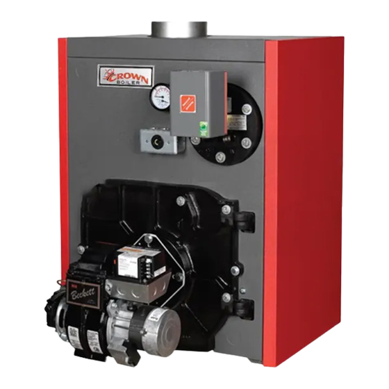
Page 7: Product Description
I Product Description The TWZ series boiler is a cast iron oil-fired water boiler designed for use in closed forced circulation heating systems. This boiler must be vented by natural draft into a lined masonry or metal chimney, or Type L vent. An adequate supply of air for combustion, ventilation and dilution of flue gases must be available in the boiler room. -
Page 8: Before Installing
TABLE 2.2: OPTIONAL TANKLESS HEATER RATINGS Tankless Heater Rating Notes: Boiler Model (Gal/min) TWZ065 2.75 1. Net Ratings are based on piping and pick-up allowances of 1.15. TWZ075 3.00 2. Burner Capacity Rating, GPH is based on #2 oil with a Gross TWZ100 3.25 Heating Value equal to 140000 BTU/Gal. -
Page 9: Locating The Boiler
If a power venter must be used, it is the responsibility of the installer and power venter manufacturer to “engineer” the power vent system. CROWN BOILER COMPANY WILL ASSUME NO RESPONSIBILITY FOR DAMAGE TO SIDING, ETC. FROM A POWER VENTED OIL- FIRED BOILER. - Page 10 FIGURE 4.0: CLEARANCES FIGURE 4.1: INSTALLATION OVER A COMBUSTIBLE FLOOR...
-
Page 11: Air For Combustion & Ventilation
Air for Combustion and Ventilation WARNING • Insufficient combustion air supply may result in the production and release of soot or deadly carbon monoxide (CO) into the home which can cause property damage, severe personal injury or death. • This boiler is not designed for use in a space that is depressurized relative to the outdoors. Operating this boiler in a depressurized space may cause property damage, severe personal injury or death. - Page 12 FIGURE 5.0: BOILER INSTALLED IN CONFINED SPACE, ALL AIR FROM INSIDE 2) Unconfined Space - Natural infiltration into the boiler room will normally provide adequate air for combustion and venti- lation without additional louvers or openings into boiler room. 3) Confined Space - Provide two openings into the boiler room, one near the floor and one near the ceiling. The top edge of the upper opening must be within 12”...
- Page 13 FIGURE 5.1: ALL AIR FROM OUTDOORS, VENTILATED CRAWL SPACE AND ATTIC FIGURE 5.2: ALL AIR FROM OUTDOORS, VIA VENTILATED ATTIC...
- Page 14 FIGURE 5.3: ALL AIR FROM OUTDOORS, USING OPENINGS INTO BOILER ROOM FIGURE 5.4: ALL AIR FROM OUTDOORS, USING HORIZONTAL DUCTS INTO BOILER ROOM...
-
Page 15: Venting
FIGURE 6.0: TYPICAL VENT SYSTEM INSTALLATION AND COMPONENTS 1) Acceptable Chimneys - The following chimneys may be used to vent a TWZ series boiler: • Listed Type L vent - Install in accordance with the manufacturer’s instructions, the terms of its listing, and applicable codes. - Page 16 2) Acceptable Vent Connectors - The following may be used for vent connectors: • Listed Type L vent. • Single Wall Galvanized Pipe - Use 0.018” (26 gauge) or heavier. 3) Chimney and Vent Connector Sizing - See Table 6.1 for minimum vent connector and chimney sizing. The vent connector size must not be smaller than boiler flue collar diameter.
-
Page 17: System Piping
VII System Piping WARNING • Install boiler so that the electrical components are protected from water (dripping, spraying, rain, etc.) during appliance operation and service (circulator replacement, etc.). • Operation of this boiler with continuous return temperatures below 120°f can cause severe heat exchanger corrosion damage. - Page 18 1) Relief valve (Required) - Mount the relief valve on the top left side of the boiler as shown in Figure 7.1 using the 3/4” nipple provided. The relief valve shipped with the boiler is set to open at 30 psi. This valve may be replaced with one having a pressure up to the “Maximum Allowable Working Pressure”...
- Page 19 FIGURE 7.2: INDIRECT WATER HEATER BOILER SIDE PIPING FIGURE 7.3: BOILER BYPASS PIPING Piping for Special Situations Certain types of heating systems have additional requirements. Some of the more common variations follow: 1) Indirect Water Heaters - Figure 7.2 shows typical indirect water heater piping. Boiler piping is the same as for any two- zone system.
- Page 20 3) Low Temperature Systems - Some systems, such as radiant tubing systems, require the system water temperature to be limited to a value below the temperature of the water leaving the TWZ. These systems also typically have return temperatures well below the 120°F minimum. Figure 7.4 illustrates the use of a heat exchanger to connect the TWZ boiler to this type of system.
-
Page 21: Tankless Heater Piping
VIII Tankless Heater Piping If the TWZ is installed with an optional tankless heater, pipe the heater as shown in Figure 8.1. The components in this system and their functions are as follows: 1) Mixing Valve (Required) - During the heating season, the water exiting the tankless heater may be 180 degrees or more. The mixing valve blends hot water leaving the tankless heater with cold water so as to maintain the hot water supplied to the fixtures at a fixed temperature. -
Page 22: Fuel Line Piping
FIGURE 8.1: TANKLESS HEATER PIPING IX Fuel Line Piping WARNING • Under no circumstances can copper with sweat style connectors be used. • Do not use compression fittings. • Oil piping must be absolutely airtight or leaks or loss of prime may result. •... - Page 23 FIGURE 9.1: ONE-PIPE GRAVITY SYSTEM Depending on the location of the fuel oil storage tank in relation to an oil burner, there are four types of oil piping systems generally being used: a) ONE-PIPE GRAVITY SYSTEM - used when a fuel oil storage tank is positioned above an oil burner fuel pump. See Figure 9.1.
- Page 24 7) Attach required piping between burner fuel pump and fuel oil storage tank. Install one fuel shut-off valve near the storage tank and second fuel shut-off valve near the oil burner fuel pump. Use heavy wall copper tubing in a continuous run. On two-pipe systems, the return line should terminate 3”...
-
Page 25: Wiring
FIGURE 9.4: TWO-PIPE LIFT SYSTEM X Wiring WARNING • All wiring and grounding must be done in accordance with the authority having jurisdiction or, in the absence of such requirements, with the National Electrical Code (ANSI/NFPA 70). • Disconnect electrical power to the boiler and heating system before servicing. Positively assure that no voltage is present. - Page 26 2) Low Voltage Connections – Low voltage field connections are located as shown in Figure 10.0 and 10.1 and are as follows: • T-T - Connect to a 24 volt heating thermostat or other “dry contacts” (such as a zone panel end switch) that close upon a call for heat.
- Page 27 FIGURE 10.0: CONNECTIONS DIAGRAM, BOILERS WITH OR LESS TANKLESS HEATER...
- Page 28 Riello 530SE: Beckett 7505: Carlin 40200: FIGURE 10.1: CONNECTIONS DIAGRAM FOR BURNER PRIMARY CONTROLS...
-
Page 29: Start-Up & Checkout
XI Start-up and Checkout Use the following procedure for initial start-up of the boiler: WARNI NG • Never attempt to fill a hot empty boiler. • Make sure that the area around the boiler is clear and free from combustible materials, gasoline, and other flammable vapors and liquids. - Page 30 20) Check the CO2 and confirm that it is between the minimum and maximum limits shown in Table 11.0. Adjust if necessary. 21) Verify that the smoke level still does not exceed #1 and that the draft over fire is -0.02 inch w.c. 22) Turn off the burner and remove pressure gauge.
- Page 31 TABLE 11.0b: CARLIN BURNER CONFIGURATION AND SETUP DATA BOILER MODEL TWZ065 TWZ075 TWZ100 TWZ090 TWZ125 TWZ150 TWZ120 TWZ175 TWZ200 BURNER MODEL EZ-1HP EZ-1HP EZ-1HP EZ-1HP EZ-1HP EZ-1HP EZ-1HP EZ-2HP STANDARD DEL. HAGO HAGO DEL. DEL. HAGO HAGO DEL. NOZZLE 1.25/60B 1.00/60B 0.55/70B 0.60/60ES 0.85/60B 0.75/60A 1.00/60A...
-
Page 32: Operation
XII Operation A. General Information This boiler uses the Hydrolevel Hydrostat® model 3250-Plus control to provide control of boiler water temperature, as well as to manage demands for up to two circulator zones. In addition, this control also provides protection against low water conditions. The 3250-Plus is used on both boilers equipped with tankless heaters and those without. - Page 33 B. Setting the Control NOTE: Settings can be checked using the TEST/SETTINGS button located on the top right of the control. See page 33 for details. 1) Setting the High Limit - The high limit is factory set at 190°F. To adjust, turn the HI TEMP dial A until the desired setting is displayed.
- Page 34 NOTE: DHW Priority: During a call from an indirect water heater, the control will de-energize the circulator contacts (C1/C2) to heat only the indirect tank ensuring an adequate supply of domestic hot water. The control will re-energize the circulator when the indirect tank is satisfied or if the boiler temperature reaches 170°F. If the indirect call continues for 45 minutes, the control will override the priority function energizing the circulator to provide space heating.
- Page 35 5) Circulator Hold Off (Enhanced Condensing Protection) - To reduce the potential for condensing, on a call for heat the control will allow the boiler to heat to 125°F prior to energizing the circulator. Once energized, the circulator will remain on for the duration of the heating call unless the boiler temperature drops below 115°F.
- Page 36 TABLE 12.2 DEFAULT SETTINGS Dial Default Feature Options Description Setting Setting Purge Inactive Thermal Pre-Purge Purge Active Degrees Fahrenheit Fahrenheit or Celsius Degrees Celsius LWCO Manual or Auto- Automatic Reset matic Reset Manual Reset Circulator operation on TT call only Circulator Options Circulator operation on ZC/ZR call only Circulator operation on call from either...
- Page 37 FIGURE 12.3 LED Legend and TEST/SETTINGS Button 5) ECONOMY - ACTIVE - Indicates that the thermal targeting function is active and the control will reduce boiler temperature to conserve fuel. The Economy feature is activated using the ECONOMY dial. (See “Setting the Economy Feature” on page 29 for more information).
-
Page 38: Service & Maintenance
XIII Service and Maintenance WARNING All boiler cleaning must be completed with the burner service switch turned off. Boilers equipped with burner swing door have a potential hazard which can cause severe property damage, personal injury or loss of life if ignored. Before opening swing door, turn off service switch to boiler to prevent accidental firing of burner outside the combustion chamber. - Page 39 WARNING The boiler must be connected to an approved chimney in good condition. Serious property damage could result if the boiler is connected to a dirty or inadequate chimney. The interior of the chimney flue must be inspected and cleaned before the start of the heating season and should be inspected periodically throughout the heating season for any obstructions.
- Page 40 Important Product Safety Information Refractory Ceramic Fiber Product Warning: The Parts list designates parts that contain refractory ceramic fibers (RCF). RFC has been classified as a possible human carcinogen. When exposed to temperatures about 1805°F, such as during direct flame contact, RFC changes into crystalline silica, a known carcinogen.
-
Page 41: Troubleshooting
XIV Trouble Shooting A. Combustion 1) Nozzles - The selection of the nozzle supplied with this boiler is the result of extensive testing to obtain the best flame shape and efficient combustion. Other brands of the same spray angle and pattern may be used but may not perform at the expected level of CO and smoke. - Page 42 B. Control System The following pages contain a trouble shooting table and flow charts for use in diagnosing control problems. When using these materials the following should be kept in mind: 1) This information is only meant to be used by a professional heating technician as an aid in diagnosing boiler problems. 2) Where applicable, follow all precautions outlined in the Section XI (Start-up and Checkout).
- Page 43 TABLE 14.0 - DIAGNOSTIC CONDITIONS Condition Possible Cause Burner will not fire See Flow Chart 1, page 42 Burner will not shut down See Flow Chart 2, page 43 Under normal operation, boiler temperature will continue to rise after the control shuts off Temperature display exceeds the burner.
- Page 44 Troubleshooting Flow Chart 1 – Burner Will Not Fire The Control is The Thermal Pre-Purge feature holds off the burner until the Does the Purging Latent control determines if the latent heat in the boiler can satisfy Display Read Heat from the the heat call.
- Page 45 Troubleshooting Flow Chart 2 – Burner Will Not Shut Down Is the The Control is Red LED Sensing (LOW WATER) Low Water. WARNING! TURN OFF POWER TO BURNER IMMEDIATELY! CAUTION – ALWAYS ALLOW A BOILER TO FULLY COOL BEFORE ADDING WATER. Recheck wiring.
-
Page 46: Parts
XV Parts QUANTITY PER BOILER OR CROWN P.N. QTY. OR CROWN KEY # DESCRIPTION P.N. HEAT EXCH ASSY. WITH COIL OPENING 1 ea. 270013 270013 270013 270014 270014 270014 270015 270015 270015 HEAT EXCH ASSY. LESS COIL OPENING 1 ea. 2700135 2700135 2700135... - Page 48 QUANTITY PER BOILER OR CROWN P.N. QTY. OR CROWN KEY # DESCRIPTION P.N. REVERSIBLE SIDE JACKET PANEL (RED) 2 ea. 270523 270523 270523 270524 270524 270524 270525 270525 270525 REAR JACKET PANEL 290220 1 ea. 1 ea. 1 ea. 1 ea. 1 ea.
- Page 50 SERVICE RECORD DATE SERVICE PERFORMED...
- Page 51 Notes...
- Page 52 Manufacturer of Hydronic Heating Products P.O. Box 14818 3633 I. Street Philadelphia, PA 19134 www.crownboiler.com...
Need help?
Do you have a question about the TWZ Series and is the answer not in the manual?
Questions and answers