
Subscribe to Our Youtube Channel
Related Manuals for Kohler 24RCLA


Summary of Contents for Kohler 24RCLA
- Page 1 Operation Residential/Light Commercial Generator Sets Models: 24RCL/A 30RCL/A 38RCLB/C Controller: RDC2 TP-6905 9/21d...
- Page 2 State of California to cause cancer and birth defects or other reproductive harm. For more information go to www.P65warnings.ca.gov Kohler strongly recommends that only factory-authorized dealers install and service the generator. Product Identification Information...
-
Page 3: Table Of Contents
Table of Contents Safety Precautions and Instructions ............Introduction . - Page 4 Table of Contents, continued 3.14 ATS Status Menu ........... . . 3.15 ATS Configuration Menu .
-
Page 5: Safety Precautions And Instructions
Safety Precautions and Instructions Accidental Starting IMPORTANT SAFETY INSTRUCTIONS. WARNING Electromechanical equipment, including generator sets, transfer WARNING switches, switchgear, and accessories, can cause bodily harm and pose life-threatening danger when improperly installed, operated, Explosion. maintained. To prevent accidents be aware of potential dangers and act Can cause severe injury or death. - Page 6 metal surface away from the battery. To Handle these materials carefully to or fall asleep. Alert others to the avoid sparks, do not disturb the battery minimize the risk of fire or explosion. possibility carbon monoxide charger connections while the battery Equip the compartment or nearby area poisoning.
- Page 7 Hazardous Voltage/ Propane (LPG)—Adequate ventilation CAUTION is mandatory. Because propane is Moving Parts heavier than air, install propane gas Welding the generator set. detectors low in a room. Inspect the DANGER cause severe electrical detectors manufacturer’s equipment damage. instructions. Welding on generator set will cause Natural Gas—Adequate ventilation is serious damage to engine electronic mandatory.
- Page 8 Hot Parts Notice Connecting the battery and the battery charger. Hazardous voltage will cause severe injury or death. NOTICE WARNING Reconnect battery correctly, Canadian installations only. positive to positive and negative to standby service connect the output of negative, to avoid electrical shock and the generator set to a suitably rated damage to the battery charger and transfer switch in accordance with...
-
Page 9: Introduction
Refer to the Installation Manual for installation instructions. Genset Model Spec Number Information in this publication represents data available Serial Number at the time of print. Kohler Co. reserves the right to Material Number change this publication and the products represented Service Duty Amps Voltage... - Page 10 Kohler dealer. generator set. Visit the Kohler Co. website at KohlerPower.com. Part Look at the labels and decals on your Kohler product Number Literature Type or review the appropriate literature or documents Specification Sheet, 24RCL G4- 228 included with the product.
-
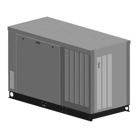
Page 11: Section 1 Service Views
Section 1 Service Views SERVICE SIDE GM90230/GM116154 ADV-8641/ADV- 9758 Cooling System Detail NON-SERVICE SIDE 1. Oil check (dipstick) 17. RDC2 controller 2. Oil fill location (on valve cover) 18. Fan fuses 3. See cooling system detail 19. Cooling air inlet (remove this panel to access coolant drain) 4. - Page 12 SERVICE SIDE GM92075 ADV-8663 Cooling System Detail NON-SERVICE SIDE 1. Oil check (dipstick) 19. Access to coolant fill (on roof) 2. Oil fill location (on valve cover) 20. Turbocharger 3. Exhaust outlet 21. Air-fuel mixer 4. Enclosure locking key (shipping location only) 22.
- Page 13 SERVICE SIDE GM116154 ADV-9759 Cooling System Detail NON-SERVICE SIDE 1. Oil check (dipstick) 19. Access to coolant fill (on roof) 2. Oil fill location (on valve cover) 20. Turbocharger 3. Exhaust outlet 21. Air-fuel mixer 4. Enclosure locking key (shipping location only) 22.
- Page 14 Notes Section 1 Service Views TP-6905 9/21...
-
Page 15: Section 2 Generator Set Operation
Section 2 Generator Set Operation 2.1 Operating Area Keep the generator set area clear. Maintain the required clearance on all sides of the generator set. Verify that there are no windows, air vents, or other WARNING openings in the building near the generator set exhaust outlet in any direction. -
Page 16: Prestart Checklist
2.2 Prestart Checklist Battery gases. Explosion can cause severe injury or death. Battery gases can cause an explosion. Do not smoke or permit flames or sparks to occur near a battery at any time, WARNING particularly when it is charging. Do not dispose of a battery in a fire. -
Page 17: Exercise The Generator Set
2.4 Generator Set Operation Short circuits. Hazardous voltage/current will cause severe injury or death. Short circuits can cause bodily injury and/or equipment damage. Do not contact electrical 2.4.1 Local Starting and Stopping connections with tools or jewelry while making adjustments or repairs. -
Page 18: Automatic Operation With Model Rxt Transfer Switch
To allow the smart engine cooldown on the RDC2 controller to operate If a Kohler Model RDT transfer switch is used, the most efficiently, set the cooldown time on the transfer engine start contacts from the ATS must be connected switch controller to zero or the minimum time allowed. -
Page 19: Exercise
2.5 Exercise 3 min. The RDC2 controller can be set to automatically run the generator set at the same time and day every week or every other week. Exercising the generator set every week or every two weeks is required in order to keep the 1 min. -
Page 20: Unloaded Full-Speed Exercise
2.5.5 Power Failure During Exercise Pressure is monitored at both low and full speeds. If the oil pressure is low, low oil pressure is displayed If the utility power is lost during an unloaded exercise, and the generator set shuts down. the ATS transfers to the emergency source, the exercise is ended and the control remains in the AUTO mode. -
Page 21: Changing The Exercise Setting
7. Press Select to save the time and move to the next 6. Press the Select button. The setting flashes to screen. show that it can be changed. For example, the hour flashes to show that the hour can be changed. 8. - Page 22 Status Overview - - > Displays 1.2 h Engine - - > - - > Metering Configuration Generator- - > Date - - > Metering and Time Genset - - > Network - - > Information Information - - > Genset - - >...
- Page 23 Genset - - > System Voltage: 240 V System System Freq: 60 Hz VR Voltage Adj: 240.0V System Phase: Single System Battery: 12 V See Section 2.5.8, Changing Next Exercise * Next Exercise the Exercise Setting HR:MN PM MM/DD/YY HR:MN PM MM/DD/YY Exercise Mode: Exercise Mode: None/Unloaded Full Sp/ Un-...
-
Page 24: Faults
TT-1584, Installation Instructions for the Programmable message displayed on the controller and refer to Interface Module, for available inputs and outputs. Figure 2-5 to identify and correct the fault condition before proceeding. Contact a Kohler authorized dealer 2.6.1 Warnings for service, if necessary. - Page 25 Fault (OnCuer Plus) Fault (RDC2) Condition Check AC Sens Loss AC Sensing Lost AC Sensing Lost. In Auto mode, generator Contact an authorized dealer for output AC sensing is lost. Detection begins 10 service. Warning seconds after crank disconnect. (1 sec.) Warning: after 1 second if no output detected Shutdwn after crank disconnect.
- Page 26 Fault (OnCuer Plus) Fault (RDC2) Condition Check Crank Lost Crank Signal Crankshaft Position Sensor (CPS) timeout error Contact an authorized dealer for Warning Lost occurred. service and provide the fault code. ECM warnings ECM warnings This group of faults includes a wide variety of Contact an authorized dealer for (any warnings (any warnings...
- Page 27 Fault (OnCuer Plus) Fault (RDC2) Condition Check Oil Pres Low Low Oil Pressure The engine ECM indicates low oil pressure. Check for signs of leaks in the Shutdwn lubrication system. Note: The low oil pressure shutdown does not protect against low oil level. Check the engine oil Check the oil level and add oil if level regularly as recommended in Section 5.
-
Page 28: Status And Notice Messages
2.6.5 Status and Notice Messages The Status and Notice messages shown in Figure 2-6 are displayed during generator set operation. These informational messages do not indicate faults. Message Type Description Advance Diagnostic Active Status During any exercise mode, shutdown occurs due to any other condition(Fault) excluding Emergency Shutdown, Main Power Overloaded Shutdown, Low Cranking Voltage Shutdown. -
Page 29: Event Log
2.7 Model RXT Transfer Switch 2.6.6 Event Log Operation The event log displays up to 1000 controller faults and notices, starting with the most recent event. Events are The RDC2 generator set/transfer switch controller numbered 1- 1000, with 1 being the most recent. Each manages automatic transfer switch (ATS) functions event is displayed with the date and time of the event, when connected to a Kohlerr Model RXT transfer switch... -
Page 30: Ats Control Sequence Of Operation
2.7.2 ATS Control Sequence of 2.7.3 Time Delays Operation Time delays are factory-set to the values shown in Figure 2-9. An authorized dealer or service technician See Figure 2-9 for time delay settings. can adjust time delays using a personal computer and Kohlerr SiteTecht software. -
Page 31: Section 3 Rdc2 Controller Operation
Section 3 RDC2 Controller Operation 3.1 RDC2 Generator Set/Transfer 3.2 Controls and Indicators Switch Controller Figure 3-1 illustrates the keypad, display, and indicators on the controller’s user interface. The generator sets are equipped with the RDC2 generator set/transfer switch controller. The RDC2 controls the following power system components: The generator set Model RXT automatic transfer switch (ATS) -
Page 32: Controller Keypad
3.2.1 Controller Keypad 3.2.2 LED Indicators The Run, Off, and Auto buttons control the generator set LEDs above the RUN, OFF, and AUTO buttons indicate as described in Figure 3-2. Use the Select, Up arrow, the mode of operation as shown in Figure 3-2. and Down arrow buttons to navigate through the menus The RDC2 controller also has a set of power system and change settings, if necessary. -
Page 33: Lcd Display
3.2.3 LCD Display The display contrast is adjustable. Navigate to the Genset System menu and step down to the Contrast The controller is equipped with a two-line x 16 character screen. Press the Select button, and then use the up and backlit liquid crystal diode (LCD) display with adjustable down arrow buttons to adjust the contrast. -
Page 34: Controller Power
Note: If no buttons are pushed, the controller exits the menus and returns to the generator set status Have controller setup and adjustment performed only by display after 5 minutes. authorized Kohler dealer authorized representative. Section 3 RDC2 Controller Operation... - Page 35 Changing Settings on the RDC2 Controller 1. Press the Select button to enter the main menu. 8. When the correct date is shown, press the Select button. The saved date is shown. Overview - - > Press: Display: Date: 1.2 h Press: Display: 03Jan2014...
-
Page 36: Controller Menus
3.6 Controller Menus 3.7 Main Menu The following sections show the RDC2 controller menus Press the Select button once to bring up the main menu. and submenus. Use the Select button and the up and Overview is displayed. See Figure 3-7. Press the down down arrow buttons to navigate the menus as shown in arrow button to step to the next menu, Engine Metering. -
Page 37: Overview Menu
3.8 Overview Menu 3.9 Engine Metering Menu The engine metering menu displays engine status information as shown in Figure 3-9. This menu displays status information only. No settings can be changed Overview - - > Active Alert from this menu. 1.2 h (if any) Eng Speed:... - Page 38 The voltage calibration mode can be entered from the Generator Metering menu. Contact a Kohler-authorized dealer for service. The Reset Calibration menu allows you to set the voltage reading back to the original value after calibration, if necessary. See Figure 3-10.
-
Page 39: Generator Set Information Menu
Kohlerr SiteTecht software is required to enter manufacturer’s recommendation for changing the oil. the generator set model number and serial numbers on Refer to Section 5, Scheduled Maintenance, for a replacement controller. Contact an authorized Kohler maintenance instructions. dealer for service. After... -
Page 40: Genset System Menu
System Voltage: 240 V System A Kohler authorized dealer or service technician can adjust these settings, if necessary. If the generator set is reconnected to a different voltage or the system settings require adjustment for some other reason, see Section System Freq: 3.5 for instructions to enable editing and change the... -
Page 41: Ats Status Menu
3.14 ATS Status Menu The ATS Status menu displays Model RXT transfer switch and source information. ATS menus appear if a Model RXT transfer switch is The voltage shown in these menus can be calibrated. connected to the generator set. If no transfer switch is Contact an authorized dealer for service if calibration is connected, or another model ATS is connected to the required. -
Page 42: Ats Configuration Menu
3.15 ATS Configuration Menu Note: The ATS Configuration menu appears only if a ATS - - > Normal Freq: Model RXT transfer switch is connected. Configuration 60.0 Hz Use the ATS Configuration submenu to check the Model RXT transfer switch system settings and time delays, and change the settings, if necessary. -
Page 43: Date And Time Menu
3.16 Date and Time Menu Date and The date and time will typically be set at controller Date: Time power-up. To change the date, time, or time format 02Dec2014 (12 hour or 24 hour), use the Date and Time menu. See Figure 3-16. -
Page 44: Networking Status Submenu
3.17.1 Networking Status Submenu If DHCP is enabled, IP parameters are not displayed. If DHCP is disabled (i.e., if a static IP address is used), the The Networking Status submenu contains settings for IP parameters are displayed. OnCuer Plus. See the OnCue Plus Software Operation Manual for information about the appropriate To enable or disable DHCP and change the IP settings, network settings for OnCue Plus. -
Page 45: Networking Configuration Submenu (Oncue Plus Password)
3.17.2 Networking Configuration Note: Use the OnCue password shown on the controller display for OnCue Plus applications. Submenu (OnCue Plus Password) The networking Configuration menu includes settings For the initial OnCue Plus setup, you will be required to reset the OnCue password on the used for communication with the Kohlerr OnCuer Plus RDC2 controller, and then enter it into the OnCue Generator Management System. -
Page 46: Rbus Information Submenu
3.17.3 RBUS Information Submenu Model RXT transfer switch The RBUS Information menu contains settings for Programmable Interface Module (PIM) remote modules that communicate with the RDC2 Load Shed Kit or RXT combined interface/load controller using RBUS protocol. This includes the management board following optional modules: Networking- - >... -
Page 47: Remote Devices Submenu
3.17.4 Remote Devices Submenu Check the status of remote devices communicating through RBUS. Device types can include: Model RXT ATS Programmable interface module (PIM) Load Shed Kit or RXT combined interface/load management board The serial numbers for the PIM and load shed kit are printed on the circuit boards inside the enclosures. -
Page 48: Programmable Interface Module (Pim) Menus
3.18 Programmable Interface A personal computer running Kohlerr SiteTecht software is required to change the input and output Module (PIM) Menus settings. Contact an authorized dealer for service. The PIM status menu displays the status of inputs and The Kohlerr OnCuer Plus Management System can be outputs connected to the programmable interface used to turn outputs on and off. -
Page 49: Load Control Menus
3.19 Load Control Menus device adds and sheds loads based on the generator current. The Load Control menu displays the status of the load The test function cycles the relays in the order of their management inputs and outputs, and allows a test of the priority. - Page 50 Notes Section 3 RDC2 Controller Operation TP-6905 9/21...
-
Page 51: Section 4 Accessories
The battery heater accessories from the generator set specification sheet kit includes a heating battery wrap and a thermostat for or by contacting an authorized Kohler dealer. Have controlled heating. accessories installed by your local authorized Kohler The heater requires a 120 VAC, 15 amp. -
Page 52: Engine Heaters
4.3 Engine Heaters 4.4 Emergency Stop Kits The emergency stop (E-stop) switch allows immediate 4.3.1 Oil Pan Heater shutdown of the generator set from a remote location. The E-stop assembly includes a shroud that allows the The oil pan heater warms the oil pan when the ambient installation of a lockout/ tagout device to lock the switch temperature falls below 4_C (40_F), making starting in the stop position. -
Page 53: Oncue Plus Generator Management System
Management System to run all of the building’s electrical equipment at the same time. The Kohler OnCue Plus Generator Management System is now included with the generator set. The The load management device automatically manages OnCue Plus System allows monitoring and control of up to six residential loads. - Page 54 Notes Section 4 Accessories TP-6905 9/21...
-
Page 55: Section 5 Scheduled Maintenance
Section 5 Scheduled Maintenance 5.1 General Maintenance Servicing the engine heater. Hot parts can cause minor personal injury or property damage. Install the heater before connecting it to power. Operating the heater before WARNING installation can cause burns and component damage. Disconnect power to the heater and allow it to cool before servicing the heater or nearby parts. - Page 56 The engine and generator set may use both American Standard and metric hardware. Use the correct size Maintenance and Service Parts. Obtain maintenance tools to prevent rounding of the bolt heads and nuts. and service parts from an authorized Kohler dealer. Section 5 Scheduled Maintenance TP-6905 9/21...
-
Page 57: Service Schedule
5.2 Service Schedule Procedure Visually Inspect Check Change Clean Test Section System Component or Procedure Frequency General Maintenance Fluid leaks Daily Engine oil level Daily Coolant level 5.6.1 Daily Obstructions or combustible materials near Weekly exhaust outlet Leaks, hissing, and gas odor Weekly Bolts and nuts for tightness Quarterly or 20 hours... -
Page 58: Lubrication System
5.3 Lubrication System 5.3.4 Oil and Filter Change WARNING 5.3.1 Oil Specifications Use oil that displays the American Petroleum Institute (API) Starburst certification mark FOR GASOLINE ENGINES on the container. Do not use straight-weight oils recommended for industrial or stationary engines. Accidental starting. - Page 59 Oil Change Procedure 4. Check for leaks. Whenever possible, drain the oil while it is still warm. a. Press the OFF button on the RDC2 generator set controller. 1. Drain the oil. b. Reconnect the generator set engine starting a. Press the OFF button on the RDC2 generator battery, negative (- ) lead last.
-
Page 60: Air Cleaner
5.4 Air Cleaner WARNING Accidental starting. 1. Air Cleaner Cover Can cause severe injury or death. GM90280 Disconnect the battery cables before Figure 5-3 Air Cleaners working generator set. Remove the negative (- ) lead first 1. Press the OFF button on the generator set. when disconnecting the battery. -
Page 61: Cooling System
D Light-headedness, dizziness Check the exhaust gas color. If the exhaust is blue or D Physical fatigue, weakness in black, contact your local authorized Kohler dealer. joints and muscles D Sleepiness, mental fatigue, Visually inspect for exhaust leaks (blowby). Check for inability to concentrate carbon or soot residue on exhaust components. -
Page 62: Checking And Filling Coolant
5.6.1 Checking and Filling Coolant 5.6.3 Draining Cooling System Maintain the coolant level in the coolant overflow bottle The radiator contains a coolant drain valve to drain the between the Hot and Cold markings. See Section 1, cooling system. When draining the coolant, remove the Service Views, for the coolant overflow bottle location. -
Page 63: Ignition System
2. Fill the radiator with the recommended coolant Service the spark plugs at the interval specified in the mixture of 50% ethylene glycol and 50% clean, service schedule using the following procedure. softened water to inhibit rust/corrosion and prevent 1. Press the OFF button on the RDC2 controller. freezing. - Page 64 Note: Ensure that the spark plug tubes are seated before installing the spark plugs. If the tubes were removed, reinstall them before installing the spark plugs. 14. Reinstall the spark plug. Do not bump the electrode against the cylinder head. Rotate the spark plug clockwise until you feel resistance.
- Page 65 Problem/Condition Means of Identification Possible Cause/Solution Gap-bridged spark Built-up deposits and gap between Oil or carbon fouling. Clean and regap the spark plug electrodes closing. plug. Oil-fouled spark plug Wet, black deposits on the insulator shell, Excessive oil entering combustion chamber through bore, and electrodes.
-
Page 66: Battery
5.8 Battery Battery short circuits. Explosion can cause severe injury or death. Short circuits can cause bodily injury and/or equipment damage. Disconnect the battery before generator Consult battery manufacturer’s instructions set installation or maintenance. Remove all jewelry before regarding battery care and maintenance. servicing the equipment. -
Page 67: Checking Electrolyte Level
5.8.1 Checking Electrolyte Level Temperature Correction Check the electrolyte level of batteries with filler caps 71.1 + .032 monthly. Remove filler caps and verify that electrolyte + .030 level reaches bottom of filler holes. Refill as necessary 65.6 + .028 EXAMPLE NO. -
Page 68: Storage Procedure
5.9 Storage Procedure 4. Check the engine coolant protection; see Section 5.6. DANGER Note: Use antifreeze capable of withstanding the lowest possible temperatures. 5. Keep spark plugs in their holes or seal spark plug holes with suitable threaded metal plugs. Hazardous voltage. -
Page 69: Section 6 Troubleshooting
Fan Fuses. Three 30 amp fan fuses are located in the computer with Kohlerr SiteTecht software. SiteTech fan fuse and relay box. See Section 1, Service Views, for software is available to Kohler authorized dealers. See location. TP-6701, SiteTecht Software Operation Manual, for more information. -
Page 70: Generator Set Troubleshooting
Battery connections reversed or poor. Check the connections. crank. Blown fuse(s). Replace the fuse. Contact an authorized Kohler dealer for service if fuse blows repeatedly. Generator set is OFF. Press the RUN button to start the engine or press AUTO to allow remote starting. -
Page 71: Controller Troubleshooting
6.6 Controller Troubleshooting Figure 6-2 contains basic troubleshooting information for the RDC2 controller. Problem Possible Cause Corrective Action Controller LCD Low or no battery voltage. Check connections. display is off. Check generator set battery. See Figure 6-1. Controller display Backlight turns off after about 1 minute with no Backlight will turn on when a button is pressed or backlight is off. - Page 72 Notes Section 6 Troubleshooting TP-6905 9/21...
-
Page 73: Appendix A Abbreviations
(2 bytes) est. estimated Canadian Electrical Code KBus Kohler communication protocol E-Stop emergency stop cert. certificate, certification, certified kilogram etc. et cetera (and so forth) cubic feet per hour exh. exhaust... - Page 74 kg/cm kilograms per square normally closed remote terminal unit centimeter National Electrical Code room temperature vulcanization kilogram-meter NEMA National Electrical read/write kg/m kilograms per cubic meter Manufacturers Association Society of Automotive kilohertz NFPA National Fire Protection Engineers Association kilojoule scfm standard cubic feet per minute newton meter kilometer...
- Page 76 KOHLER CO., Kohler, Wisconsin 53044 Phone 920-457-4441, Fax 920-459-1646 TP-6905 9/21d For the nearest sales/service outlet in the US and Canada, phone 1-800-544-2444 KOHLERPower.com E 2014 Kohler Co. All rights reserved.
Need help?
Do you have a question about the 24RCLA and is the answer not in the manual?
Questions and answers