Subscribe to Our Youtube Channel
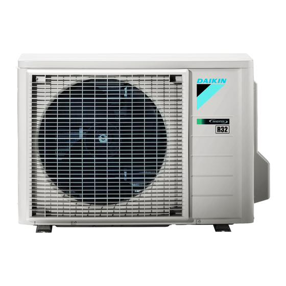
Summary of Contents for Daikin RXM42M3V1B9
- Page 1 INSTALLATION MANUAL R32 Split Series Models RXM42M3V1B9 RXM50M3V1B9 RXM60M3V1B9 ARXM50M3V1B9...
- Page 2 3P475203-5A...
- Page 3 2P427092-9H...
- Page 4 2P427092-9H...
-
Page 5: Safety Precautions
Safety Precautions Read the precautions in this manual This appliance is filled with R32. carefully before operating the unit. • The precautions described herein are classified as WARNING and CAUTION. They both contain important information regarding safety. Be sure to observe all precautions without fail. •... -
Page 6: Accessories Supplied With The Outdoor Unit
- name, address and day & night telephone numbers for obtaining service. In Europe, EN378 provides the necessary guidance for this logbook. • Only use accessories, optional equipment and spare parts made or approved by DAIKIN. Accessories Accessories supplied with the outdoor unit:... -
Page 7: Operation Limits
Operation limits Use the system in the following temperature and humidity ranges for safe and effective operation. Cooling Heating Outdoor temperature –10~46°C –15~24°C Indoor temperature 18~32°C 10~30°C Indoor humidity ≤80% To avoid condensation and water dripping out of the unit. If the temperature or the humidity is beyond these conditions, safety devices may be put in action and the air conditioner may not operate. -
Page 8: Outdoor Unit Installation Drawings
Outdoor Unit Installation Drawings Max. allowable piping length Min. allowable piping length 1.5m Wrap the insulation Max. allowable piping height pipe with the finishing Additional refrigerant tape from bottom to top. required for refrigerant 20g/m pipe exceeding 10m in length. Gas pipe O.D. -
Page 9: Precautions On Installation
Installation Guidelines • Where a wall or other obstacle is in the path of outdoor unit’s inlet or outlet airflow, follow the installation guidelines below. • For any of the following installation patterns, the wall height on the outlet side should be 1200mm or less. Wall facing one side Wall facing two sides More than 100... -
Page 10: Flaring The Pipe End
Outdoor Unit Installation Flaring the pipe end 1) Cut the pipe end with a pipe cutter. (Cut exactly at right angles.) Remove burrs. 2) Remove burrs with the cut surface facing downward so that the chips do not enter the pipe. Flaring Set exactly at the position shown below. -
Page 11: Purging Air And Checking Gas Leakage
Outdoor Unit Installation Purging air and checking gas leakage • When piping work is completed, it is necessary to purge the air and check for gas leakage. WARNING • Do not mix any substance other than the specified refrigerant (R32) into the refrigeration cycle. •... -
Page 12: Charging Additional Refrigerant
Outdoor Unit Installation Charging refrigerant Check the type of refrigerant to be used (on the machine nameplate). Fill from the gas pipe in liquid form. 1-1. Charging additional refrigerant • If the total length of refrigerant piping exceeds 10m, add refrigerant. •... -
Page 13: Refrigerant Piping Work
Outdoor Unit Installation Refrigerant piping work 7-1 Cautions on pipe handling Wall Be sure to 1) Protect the open end of the pipe against dust and moisture. place a cap. 2) All pipe bends should be as gentle as possible. Use a pipe bender Rain If no flare cap is for bending. -
Page 14: Pump Down Operation
Outdoor Unit Installation 7-3 Piping diagram Piping diagram for RXM60M3V1B9 PED categories of equipment - High pressure switches: category IV; Compressor: category II; Other art. 4§3 equipment. NOTE: When the high pressure switch is activated it must be reset manually by a qualified person. Pump Down Operation In order to protect the environment, be sure to pump down when relocating or disposing of the unit. -
Page 15: Facility Setting (Cooling At Low Outdoor Temperature)
Pump Down Operation WARNING The unit is accompanied with the label below. Please read the following instructions carefully. • When the refrigeration circuit has a leak, do not execute pump down with the compressor. • Use recovery system into separate cylinder. WARNING •... - Page 16 Wiring WARNING • Do not use tapped wires, stranded wires, extension cords, or starburst connections, as they may cause overheating, electrical shock, or fire. • Do not use locally purchased electrical parts inside the product. (Do not branch the power for the drain pump, etc., from the terminal block.) Doing so may cause electric shock or fire.
- Page 17 Wiring Observe the notes mentioned below when wiring to the power supply terminal block. Precautions to be taken for power supply wiring. CAUTION • When connecting the wires to the terminal block using a single core wire, be sure to perform curling. Problems with the work may cause heat and fires.
-
Page 18: Unified Wiring Diagram Legend
Wiring Wiring diagram Unified Wiring Diagram Legend For applied parts and numbering refer to the wiring diagram sticker supplied on the unit. Part numbering is realized by Arabic numbers in ascending order for each part and is represented in the overview below by symbol “*” in the part code. CIRCUIT BREAKER CIRCUIT BREAKER PROTECTIVE EARTH... -
Page 19: Standby Electricity Saving
Standby Electricity Saving The standby electricity saving function turns off power supply to the outdoor unit and sets the indoor unit into standby electricity saving mode, thus reducing the power consumption of the air conditioner. The standby electricity saving function works on the following indoor units. For FTXM, FVXM types. -
Page 20: Trial Operation And Testing
Trial Operation and Testing Trial operation and testing 1-1 Measure the supply voltage and make sure that it falls in the specified range. 1-2 Trial operation should be carried out in either cooling or heating mode. For heat pump •... - Page 24 3P386698-4L 2017.04...


Need help?
Do you have a question about the RXM42M3V1B9 and is the answer not in the manual?
Questions and answers