Table of Contents
Advertisement
Quick Links
Advertisement
Table of Contents

Related Manuals for Sony CDX-626


Summary of Contents for Sony CDX-626
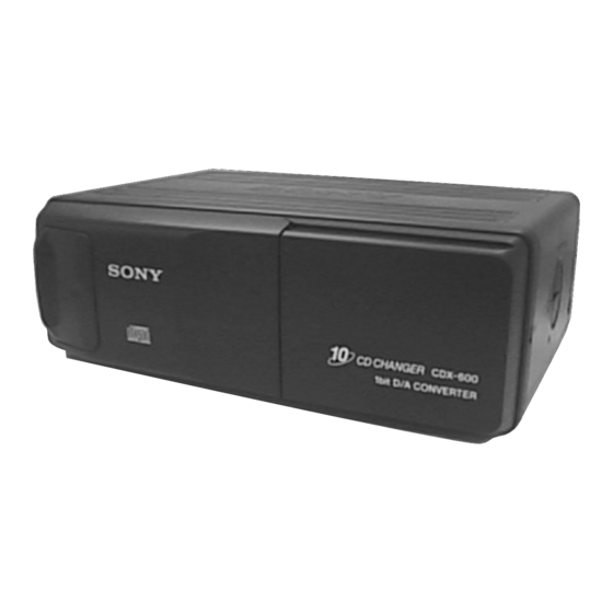
- Page 1 CDX-600/606/626 SERVICE MANUAL US Model CDX-600/606 Canadian Model AEP Model UK Model CDX-600 E Model CDX-626 Photo: CDX-600 Model Name Using Similar Mechanism CDX-505RF CD Drive Mechanism Type MG-250C-137 Optical Pick-up Name KSS-521A/J2N SPECIFICATIONS COMPACT DISC CHANGER MICROFILM...
-
Page 2: Table Of Contents
SUR LES DIAGRAMMES SCHÉMATIQUES ET LA LISTE DES PIÈCES SONT CRITIQUES POUR LA SÉCURITÉ DE FONCTIONNEMENT. NE REMPLACER CES COM- POSANTS QUE PAR DES PIÈCES SONY DONT LES Magazine ass’y NUMÉROS SONT DONNÉS DANS CE MANUEL OU DANS LES SUPPLÉMENTS PUBLIÉS PAR SONY. -
Page 3: General
SECTION 2 This section is extracted from instruction manual. GENERAL – 3 – – 4 –... - Page 4 – 5 –...
-
Page 5: Disassembly
SECTION 3 DISASSEMBLY Note: Follow the disassembly procedure in the numerical order given. COVER (UPPER) , FRONT PANEL ASS’Y 1 screw 1 screw (PTT2.6 × 6) (PTT2.6 × 6) 2 cover (upper) 3 lever (FL) 1 screw 1 screw (PTT2.6 × 6) (PTT2.6 ×... - Page 6 JACK BOARD Remove the jack board of the arrow. 1 ground point screw (PTT2.6 × 6) 2 jack board MAIN BOARD 1 main flexible board (CNJ12) 6 three screws (FP) 7 main board 2 connector (CNP301) 3 screw 5 two precision screws (PTT2 ×...
- Page 7 ELEVATOR MOTOR ASS’Y (M104) 1 screw (PTT2 × 3) 2 bracket (EVM) 3 elevator motor ass’y (M104) ESCUTCHEON 3 two claws 2 Remove the claw of the arrow A . 4 Remove the ditch of the arrow B . 5 Remove the escutcheon of the arrow C .
- Page 8 CASE (UPPER) ASS’Y 3 Remove the edge of the arrow A . 1 three screws (PTT2 × 4) 1 two screws (PTT2 × 4) 4 Remove the case (upper) ass’y of the arrow B . 1 screw (PTT2 × 4) CHASSIS ASS’Y 3 chassis ass’y 1 two polyethylene washers...
- Page 9 RF BOARD 1 OP flexible board 2 two screws (CNJ11) (PS2 × 4) 2 two screws (PS2 × 4) 5 RF board 4 connector (CNP52) 4 two connectors (CNP11, 53) SLED MOTOR ASS’Y (M102) , OPTICAL PICK-UP (KSS-521A/J2N) 1 two screws 2 sled motor ass’y (ESCUTCHEON) (M102)
- Page 10 SW BOARD, SPINDLE MOTOR ASS’Y (M101) 8 two screws (P1.7 × 2.2) 3 spring (chucking) 6 retainer (disc) 1 screw (P2 × 2.2) 4 screw (P2 × 2.2) 5 bracket (CP) 9 Remove the spindle motor ass’y (M101) 2 SW board of the arrow.
-
Page 11: Mechanism Deck Assembly
SECTION 4 MECHANISM DECK ASSEMBLY Note: Follow the assembly procedure in the numerical order given. OPTICAL PICK-UP COMPLETE ASS’Y 1 Move the lever (LOCK 3) in direction A , and return it a little in direction B from the position where the chuck plate is moved chuck plate down to the lower limit. - Page 12 OPERATION CHECK 1 Confirm that the slider moves in direction C to move down the chuck plate if the gear (LOAD 1) is rotated in direction A or the chuck plate moves up and the slider moves in direction D if the gear is rotated in direction B .
-
Page 13: Mechanical Adjustments
SECTION 5 MECHANICAL ADJUSTMENTS • Elevator Height (Address) Adjustment Note: This adjustments is necessary when the system controller (IC302), Adjustment Method: variable resistor (RV301), slider (R), slider (L), or chassis (ELV) 1. Connect this set to the master unit (e.g. MDX-C670/ was replaced for any repair. -
Page 14: Electrical Adjustments
SECTION 6 ELECTRICAL ADJUSTMENTS Note: • TRACKING OFFSET CHECK 1. Perform adjustments as given. 2. Power supply voltage: DC14.4 V (more than 3A). [RF BOARD] – Conductor Side – oscilloscope • FOCUS BIAS CHECK CNJ12 [RF BOARD] – Conductor Side – –... - Page 15 • FOCUS GAIN ADJUSTMENT • When gain is lowered... (COARSE ADJUSTMENT) The set does not play because of no focus operation. This adjustment is to be performed when replacing the following • When gain is highered... parts. Operation noise is heard due to a scratch or a dust, then opera- •...
-
Page 16: Diagrams
SECTION 7 DIAGRAMS 7-1. NOTES FOR PRINTED WIRING BOARD AND SCHEMATIC DIAGRAM Note on Printed Wiring Board: Note on Schematic Diagram: • X : parts extracted from the component side. • All capacitors are in µF unless otherwise noted. pF: µµF •... - Page 17 • Waveforms – RF Board – – MAIN Board (1/2) – – MAIN Board (2/2) – 1 IC11 #£ (RF O) 1 IC101 @¶ (MDP) 6 IC401 !£ (MCK) 500 mV/DIV, 500 ns/DIV 2.5 Vp-p 6 Vp-p 1.4 Vp-p 7.6 µ s 59.5 ns 2 IC11 2 (FEI) 2 IC101 %º...
-
Page 18: Printed Wiring Boards - Rf Section
CDX-600/606/626 7-2. PRINTED WIRING BOARDS – RF Section – • Semiconductor Location Ref. No. Location IC11 IC51 IC52 (Page 24) – 19 – – 20 –... -
Page 19: Schematic Diagram - Rf Section
CDX-600/606/626 7-3. SCHEMATIC DIAGRAM – RF Section – • See page 18 for Waveforms. • See page 31 for IC Block Diagrams. (Page 27) The components identified by mark ! or dotted Les composants identifiés par une marque ! sont line with mark ! are critical for safety. -
Page 20: Printed Wiring Boards - Main (Component Side)/Jack Board
CDX-600/606/626 7-4. PRINTED WIRING BOARDS – MAIN (Component Side)/JACK Board – • Semiconductor Location Ref. No. Location D201 D202 D203 D204 D205 D206 D207 D301 F-10 D311 D416 D417 D501 D502 D503 D504 D505 (Page 20) IC101 B-11 IC202 IC204 IC301 IC302 E-11... -
Page 21: Printed Wiring Board - Main Board (Conductor Side)
CDX-600/606/626 7-5. PRINTED WIRING BOARD – MAIN Board (Conductor Side) – • Semiconductor Location Ref. No. Location IC201 IC203 Q201 – 25 – – 26 –... -
Page 22: Schematic Diagram - Main Section (2/2)
CDX-600/606/626 7-6. SCHEMATIC DIAGRAM – MAIN Section (1/2) – • See page 18 for Waveforms. • See page 33 for IC Block Diagrams. (Page 22) – 27 – – 28 –... - Page 23 CDX-600/606/626 7-7. SCHEMATIC DIAGRAM – MAIN Section (2/2) – • See page 18 for Waveforms. • See page 33 for IC Block Diagrams. – 29 – – 30 –...
- Page 24 • IC Block Diagrams IC52 BA6287F – RF Board – OUT1 IC11 CXA1992BR 33 32 31 30 OUT2 PD 2 PD 1 I-V AMP I-V AMP DRIVER DRIVER RF SUMMING FOCUS OK COMPARATOR VREF CONTROL LOGIC LASER POWER CONTROL IFB1 – IFB6 POWER PEAK/BOTTOM MIRR...
- Page 25 IC204 BA8272F-E2 IC301 BA6287F OUT1 RESET OUT2 SWITCH DRIVER DRIVER VREF CONTROL LOGIC POWER SAVE IC401 TC9464FN-EL 14 13 MICROCOMPUTER INTERFACE INTERFACE CIRCUIT CIRCUIT DIGITAL FILTER CIRCUIT TIMING ATTENUATOR OPERATIONAL CIRCUIT GENERATOR DEEMPHASIS FILTER CIRCUIT D-∆ MODULATION CIRCUIT TEST OUTPUT OUTPUT CIRCUIT CIRCUIT...
-
Page 26: Ic Pin Function Description
25 to 29 — Not used (open) System reset signal input from the reset signal generator (IC202) and SONY bus interface (IC204) RESET “L”: reset For several hundreds msec. after the power supply rises, “L” is input, then it changes to “H”... - Page 27 Pin No. Pin Name Function SCOR Subcode sync (S0+S1) detection signal input from the CXD2530Q (IC101) SENS2 Internal status signal (sense signal) input from the CXA1992BR (IC11) Motor drive signal (elevator up direction) output to the elevator motor drive (IC301) “L”...
-
Page 28: Exploded Views
X-3376-770-1 DOOR ASSY (CDX-606) * 16 3-022-694-01 HOLDER (TR3) X-3376-771-1 DOOR (600T) ASSY (CDX-600) 3-935-636-11 SCREW (FP) X-3376-773-1 DOOR (626T) ASSY (CDX-626) X-3373-215-1 ARM (FL) ASSY (CDX-606) 3-376-464-11 SCREW (+PTT 2.6X6), GROUND POINT X-3375-357-1 ARM (FLT) ASSY (CDX-600/626) 3-022-002-62 PANEL (T), FRONT (CDX-600) - Page 29 (2) MECHANISM DECK SECTION-1 (MG-250C-137) Ref. No. Part No. Description Remark Ref. No. Part No. Description Remark X-3375-497-1 CHASSIS (U) SUB ASSY 4-965-759-01 WASHER, POLYETHYLENE 3-024-161-01 SPRING (SUT) 3-011-997-01 SPRING (STOPPER. LOWER) – 37 –...
- Page 30 (3) MECHANISM DECK SECTION-2 (MG-250C-137) M104 Ref. No. Part No. Description Remark Ref. No. Part No. Description Remark 3-024-170-01 SPRING (SB), TENSION X-3375-498-4 CHASSIS (D) SUB ASSY * 102 3-024-172-01 BRACKET (EVM) M104 A-3301-123-A ELJ MOTOR ASSY (ELEVATOR) – 38 –...
- Page 31 (4) MECHANISM DECK SECTION-3 (MG-250C-137) M103 Ref. No. Part No. Description Remark Ref. No. Part No. Description Remark * 151 3-024-150-01 RETAINER (CHM) 3-010-268-01 SPRING (DH), TENSION * 152 X-3375-445-1 BRACKET (CHM) ASSY * 161 A-3290-194-F CHASSIS (EVY) (MAIN) ASSY 3-010-270-01 COVER (CHM) 3-010-254-01 SHAFT (ROTARY PREVENTION C) 3-321-813-01 WASHER, COTTER POLYETHYLENE...
- Page 32 (5) MECHANISM DECK SECTION-4 (MG-250C-137) not supplied M101 not supplied M102 The components identified by Les composants identifiés par une mark ! or dotted line with marque ! sont critiques pour la mark ! are critical for safety. sécurité. Replace only with part num- Ne les remplacer que par une pièce ber specified.
- Page 33 SECTION 9 JACK MAIN ELECTRICAL PARTS LIST NOTE: • Due to standardization, replacements in the • Items marked “*” are not stocked since they The components identified by mark ! or dotted line with mark parts list may be different from the parts speci- are seldom required for routine service.
- Page 34 MAIN Ref. No. Part No. Description Remark Ref. No. Part No. Description Remark < DIODE > R104 1-216-061-00 METAL CHIP 3.3K 1/10W R105 1-216-061-00 METAL CHIP 3.3K 1/10W D201 8-719-210-33 DIODE EC10DS2 D202 8-719-210-33 DIODE EC10DS2 R106 1-216-073-00 METAL CHIP 1/10W D203 8-719-988-61 DIODE 1SS355TE-17...
- Page 35 Ref. No. Part No. Description Remark Ref. No. Part No. Description Remark A-3313-586-A RF BOARD, COMPLETE IC51 8-759-071-79 IC BA6297AFP IC52 8-759-040-83 IC BA6287F ******************* < CAPACITOR > < TRANSISTOR > 1-163-009-11 CERAMIC CHIP 0.001uF 8-729-141-48 TRANSISTOR 2SB624-BV345 1-113-500-11 TANTAL. CHIP 100uF 1-163-038-00 CERAMIC CHIP 0.1uF...
- Page 36 Description Remark < VARIABLE RESISTOR > 3-865-035-11 MANUAL, INSTRUCTION (ENGLISH)(CDX-606) RV14 1-238-091-11 RES, ADJ, CERMET 3-865-036-11 MANUAL, INSTRUCTION (ENGLISH, FRENCH, SPANISH, CHINESE) (CDX-626) < SWITCH > A-3291-950-C MAGAZINE ASSY ************************************************************ SW11 1-762-946-12 SWITCH, PUSH (1 KEY) (CHUCKING END DETECT) PARTS FOR INSTALLATION AND CONNECTIONS...
Need help?
Do you have a question about the CDX-626 and is the answer not in the manual?
Questions and answers