Table of Contents
Advertisement
Quick Links
Advertisement
Table of Contents

Subscribe to Our Youtube Channel
Related Manuals for BERG KOMPBERG ZXF132


Summary of Contents for BERG KOMPBERG ZXF132
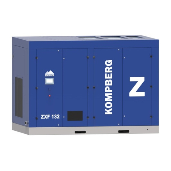
- Page 1 OPERATING AND MAINTENANCE MANUAL Oil-free screw compressor KOMPBERG ZXF132...
- Page 2 Ladies and Gentlemen, We heartily welcome you among our valued Customers and thank you for your trust to purchase the BERG compressor. We are sure you will be fully satisfied with both the choice you have made and the cooperation you started with us. Our compressors are machines of top quality, which is the guarantee for a long years and reliable performance.
-
Page 3: Table Of Contents
Table of contents 1. Information concerning the document ......................1.1. Scope and intended use of the manual ....................... 1.2. Intended use of the compressor and conditions of safe use ..............1.3. Qualification requirements for operation of the compressor..............1.4. Operation ..............................1.5. -
Page 4: Information Concerning The Document
1. Information concerning the document This operating and maintenance manual is an integral part of the machine. It includes the information necessary to start, operate and maintain the compressor and requirements for its safe operation. Following the manual rules will help you: •... -
Page 5: Qualification Requirements For Operation Of The Compressor
Follow the periodic inspection schedule during both warranty period and after its completion. Regular performance of periodic inspections is necessary to ensure the required reliability and life of the BERG equipment. The inspections performed according the schedule reduce the number of repairs and their cost. -
Page 6: Other Remarks And Instructions
2. Operating safety rules The present rules are valid for BERG screw compressors. In addition to the general health and safety at work andthe Office of Technical Inspection (UDT) regulations applicable to compressors, their assemblies and accessories, the safety instructions given below should be followed in particular. -
Page 7: Basic Requirements For Safe Transport And Positioning Of The Screw Compressor
2.1. Basic requirements for safe transport and positioning of the screw compressor In addition to the general health and safety at work and the Office of Technical Inspection (UDT) regulations, the following rules must be observed: Use only the lifting equipment that is compliant with the H&S and UDT regulations to lift the compressor. -
Page 8: Other Hazards
- It is prohibited to remove the green and yellow protective conductors that prevent electric shock. - No additional equipment can be mounted on the air receiver(except for the equipment allowed for use by the manufacturer). - No welding operations or any other repairs can be performed on the air receiver. - The plugs and other air receiver accessories can only be removed after the air receiver depressurisation to the ambient pressure. -
Page 9: Technical Data
3. Technical data Type KOMPBERG ZXF132 Overpressure* 440 ÷ 1143 Min ÷ Max capacity /min 7,33 ÷ 19,05 Weight 4500 kg Dimensions (LxWxH) 3400x2100x2400 Compressed air connection Ambient temperature +5 ÷ +40 +10 do 15 C above ambient Compressed air temperature... -
Page 10: Setting
To improve ventilation in the compressor room, the machine can be connected to the discharge air duct; in such case, please contact BERG. The suitable ventilation in a room will prevent the possibility of negative pressure generation or undesired temperature increase. -
Page 11: Requirements Concerning Electrical System
Each BERG compressor should be connected to the compressed air network by using a flexible conduit or flexible connector (axial expansion joint) and shut-off valve. -
Page 12: Screw Compressor Operating Description And Drawings
5. Screw compressor operating description and drawings Air filter 29 Pressure sensor Suction valve 30 Temperature sensor First stage 31 Temperature sensor Venturi nozzle 32 Temperature sensor First stage cooler 33 Safety valve Cyclone separator 34 Pressure sensor Second stage 35 Temperature sensor Venturi nozzle 36 Pressure sensor... - Page 18 The compressor is equipped with two stage air end ("of dry-type") without oil injection into the compression chamber with the bearings and gearing and the coat of the high pressure part are lubricated and cooled with oil. POWER AND CONTROL The compressor (screw air-end) is driven by an electric motor through a flexible coupling .
-
Page 19: Technological Diagram
Technological diagram Air filter 19 Oil filter Suction valve 20 Overflow valve First stage 21 Oil manifold Venturi nozzle 22 Vent filter First satage cooler 23 Hydraulic cylinder Cyclone separator 24 Solenoid valve Second stage 25 Solenoid valve Venturi nozzle 26 Air filter pollution sensor Second stage cooler 27 Temperature sensor... - Page 20 MEASURING SENSORS The following temperature sensors and pressure transducer are installed in the compressor installation: (26) - air filter pollution sensor, (27) - temperature sensor - realizes the measurement of the compressed air temperature after the I stage (3), (30) - temperature sensor - realizes the measurement of the compressed air temperature after cooling in the cooler (5), (29) - pressure transducer - performs measurement of air pressure after the cooler (5),...
- Page 21 Screw air end CD14D1 Suction regulator Operating panel Controller instruction is an integral part of the OMM of compressor KOMPBERG ZXF132...
-
Page 22: Start-Up
6. Start-up 6.1. Start-up preparation Each compressor unit is tested in the factory and carefully inspected to ensure proper machine performance and meeting the specifications declared. Strictly obey the following rules before starting the machine for the first time: Get thoroughly familiar with the compressor Operating and Maintenance Manual and the Warranty Book. -
Page 23: Restart (After Longer Downtime)
Rotating direction of CD14D1 Proper direction of screw air end rotation 6.2. Restart (after longer downtime) Follow the procedure described below to start the compressor which has been out of use or stored for over 3 months: Check if there is no water in the screw assemble. Turn the compressor shaft several times by hand in the rotating direction. -
Page 24: Maintenance And Checks
Use only original spare parts. For cleaning purposes never use flammable or corrosive solvents that could damage the machine components. Take appropriate safety measures against toxic vapours from cleaning agents. Biodegradable detergents should be used. The workplace must be kept absolutely clean when maintenance work is carried out. Do not allow any parts to get contaminated. -
Page 25: Warranty And Post-Warranty Checks
7.2.4 Warranty and post-warranty checks -change the filter mat at the cooling air inlet, -change the air filter cartridge, -check electric clamp terminals, fasten if necessary, -clean the air and oil cooler ribs, every 2000 test the non-return valve for proper functioning, work hours check the condition of elastic coupling, or after 1 year... -
Page 26: Cleaning Or Replacing The Filter Mats
7.3.2 Cleaning or replacing the filter mats. Filter mat is placed at the inlet into the housing. If the filter mat get dirty, cooling of the compressor may be insufficient. Maintenance operations: Carefully, without tools, remove the filter mat from the housing. Thoroughly vacuum or flick the mat. -
Page 27: Oil Level
Rub some oil onto the gasket of the new filter before screwing it in. Fill the new filter, held vertically, with the same type of oil as that in the separator tank. Then screw the filter in by hand, without using any tool. Start the compressor and check for leaks. -
Page 28: Handling Wastes Produced While Operating The Compressor
Kinematic viscosity acc. ISO VG 46 Kinematic viscosity at 40 C 41,4-50,6 Oil of the specified parameters is the only acceptable oil for use in BERG oil-free screw compressors (oil - part No. COL0069 ie.package of 10 L produced 7.3.6. Handling wastes... -
Page 29: Electric Motor
Maintenance procedure: Stop the compressor, close the pressure conduit valve. Lower the overpressure in the screw assembly body till reaches the atmospheric pressure (to lower the overpressure inside the screw assembly body wait about 5 minutes after switching off the compressor, Safeguard the compressor from restarting by an unauthorized person, e.g. -
Page 30: Safety Valve
Safety valve 7.3.9 The safety valves fulfil an important function in pressure equipment and systems. They require particularly careful and professional service. Any operational shortcomings may damage the valve mechanism, and consequently damage the entire pressure unit. Therefore, during the equipment operation particular attention should be paid to the following: Correct setting of the safety valve, appropriate to the operating parameters of the equipment being protected,... - Page 31 difficult ambient temperature too heat the room up to reach at least +5°C compressor start non return valve fault call the service wrong rotation wrong phase sequence swap two phase leads in the compressor direction terminal block or in the electric cabinet oil temperature ambient temperature ensure adequate ventilation in the room.
-
Page 33: Consumables For One Year Guarantee
9. Consumables for one year guarantee Name Part number Quantity Air filter BL 480061 + BL 480048 Compressed air filter cartridge Element for F 24 GW ( 24 G ) Oil filter BÖ 480001 Coupling insert BS 482047 Öl 480069* 40 l Thermostat cartridge BS 488580...
Need help?
Do you have a question about the KOMPBERG ZXF132 and is the answer not in the manual?
Questions and answers