Table of Contents
Advertisement
Quick Links
Advertisement
Table of Contents

Related Manuals for BERG KOMPBERG ZXF55


Summary of Contents for BERG KOMPBERG ZXF55
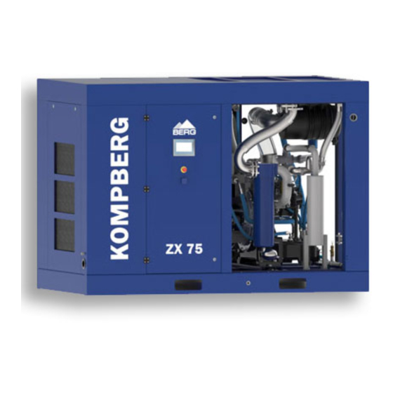
- Page 1 OPERATING AND MAINTENANCE MANUAL Oil-free screw compressor KOMPBERG ZX75...
- Page 2 Ladies and Gentlemen, We heartily welcome you among our valued Customers and thank you for your trust to purchase the BERG compressor. We are sure you will be fully satisfied with both the choice you have made and the cooperation you started with us. Our compressors are machines of top quality, which is the guarantee for a long years and reliable performance.
-
Page 3: Table Of Contents
Table of contents 1. Information concerning the document ................4 1.1. Scope and intended use of the manual ..................4 1.2. Intended use of the compressor and conditions of safe use ............4 1.3. Qualification requirements for operation of the compressor............5 1.4. -
Page 4: Information Concerning The Document
1. Information concerning the document This operating and maintenance manual is an integral part of the machine. It includes the information necessary to start, operate and maintain the compressor and requirements for its safe operation. Following the manual rules will help you: ▪... -
Page 5: Qualification Requirements For Operation Of The Compressor
Follow the periodic inspection schedule during both warranty period and after its completion. Regular performance of periodic inspections is necessary to ensure the required reliability and life of the BERG equipment. The inspections performed according the schedule reduce the number of repairs and their cost. -
Page 6: Other Remarks And Instructions
2. Operating safety rules The present rules are valid for BERG screw compressors. In addition to the general health and safety at work and the Office of Technical Inspection (UDT) regulations applicable to compressors, their assemblies and accessories, the safety instructions given below should be followed in particular. -
Page 7: Basic Requirements For Safe Transport And Positioning Of The Screw Compressor
The limit values may not be changed by the user. The manufacturer accepts no responsibility for any personal injuries, damage of equipment or the compressor itself, at present and in the future, resulting from user’s negligence and failure to observe the installation, operation and maintenance requirements contained herein. No responsibility is also taken for failure to observe valid safety standards relating to the equipment and qualified staff. -
Page 8: Operating Safety Requirements
2.2. Operating safety requirements In addition to the requirements contained in the sections: Screw compressor operation description; Start up; Maintenance; the following rules should be observed. The compressor is only designed to compress air. All safety equipment must be in place while operating the machine. The factory-mounted safety equipment must not be removed. -
Page 9: Meaning Of Pictograms
2.4. Meaning of pictograms Pictograms (safety symbols) located on and inside the compressor are described below. Explanation is provided below any of them. For technical reasons, it is not always possible to attach the pictograms in the very vicinity of the points of risk. -
Page 10: Setting
BERG. The suitable ventilation in a room will prevent the possibility of negative pressure generation or undesired temperature increase. When there are any problems in ensuring the suitable ventilation in a room, please contact BERG. -
Page 11: Requirements Concerning Electrical System
Each BERG compressor should be connected to the compressed air network by using a flexible conduit or flexible connector (axial expansion joint) and shut-off valve. -
Page 12: Screw Compressor Operating Description
5. Screw compressor operating description 5.1. Screw compressor KOMPBERG ZX75 – operating description General view of an oil-free screw compressor KOMPBERG ZX75... - Page 13 The compressor is equipped with two stage air end ("of dry-type") without oil injection into the compression chamber with the bearings and gearing and the coat of the high pressure part are lubricated and cooled with oil. POWER AND CONTROL The compressor (screw air-end) is driven by an electric motor through a flexible coupling .
-
Page 14: Technological Diagram
Technological diagram Air filter Oil filter Suction valve Overflaw valve First stage Oil distributor Venturi nozzFirst stage coolerle Vent filter First satage cooler Hydraulic cylinder Cyclone separator Solenoid valve 2nd stage Solenoid valve with time system Venturi nozzle Air filter pollution sensor stage cooler Temperature sensor Check valve... - Page 15 MEASURING SENSORS The following temperature sensors and pressure transducer are installed in the compressor installation: (39) - air filter pollution sensor, (33) - temperature sensor - realizes the measurement of the compressed air temperature after the I stage (3), (35) - temperature sensor - realizes the measurement of the compressed air temperature after cooling in the radiator (6), (34) - pressure transducer - performs measurement of air pressure after the radiator (6), (38) - temperature sensor - realizes air temperature measurement after the II stage (8),...
- Page 16 After stopping the compressor with the EMERGENCY STOP (STOP AWARYJNY) button and after the supply voltage is switched off and on, the compressor can be started by unlatching the EMERGENCY STOP (STOP AWARYJNY) button and pressing the START button. The compressor is provided with an additional protective function which prevents machine start when any of parameters given in Tab.[Technical data] is exceeded.
-
Page 17: Start-Up
Suction regulator Operating panel Controller instruction is an integral part of the OMM of compressor KOMPBERG ZX75 6. Start-up 6.1. Start-up preparation Each compressor unit is tested in the factory and carefully inspected to ensure proper machine performance and meeting the specifications declared. Strictly obey the following rules before starting the machine for the first time: Get thoroughly familiar with the compressor Operating and Maintenance Manual and the Warranty Book. -
Page 18: Restart (After Longer Downtime)
Check if all doors/covers are closed. Open the valve that shuts off the compressor from compressed air system. Check the “EMERGENCY STOP” button position. Switch on the compressor power supply. When the compressor and compressed air system condition is checked, you can proceed with starting the compressor. -
Page 19: Maintenance
7. Maintenance 7.1 General requirements To ensure proper functioning, the compressor must undergo maintenance procedures. The following general requirements must be met while performing the maintenance: Place the warning sign as shown below in a visible location, while the maintenance work is in progress: WARNING MACHINE UNDER REPAIR... -
Page 20: Maintenance And Checks
7.2. Maintenance and checks 7.2.1 Maintenance at the beginning of compressor use, after oil and drive belts (if present) change Maintenance interval Operation after 2 work hours check oil level in the receiver, top it up if necessary, after 2 work days check oil level in the receiver, top it up if necessary, after 1 week of work check oil level in the receiver, top it up if necessary,... -
Page 21: Basic Components Requiring Maintenance. Maintenance Operations
7.3. Basic components requiring maintenance. Maintenance operations. 7.3.1. Air filter cartridge The filter cartridge can't be soaked in oil or other liquids. Change the filter cartridge every 2000 work hours or once a year. In case of highly contaminated ambient air, the cartridge must be cleaned or replaced more frequently Maintenance procedure: Stop the compressor and close the pressure conduit valve. -
Page 22: Oil Filter
7.3.3. Oil filter Change the oil filter every 8000 hours or once a year. screwing out screwing in Oil filter - maintenance Maintenance procedure: Stop the compressor and close the pressure conduit valve. Reduce the overpressure in the screw assembly body and oil system to reach the atmospheric pressure (see the oil pressure manometer / microprocessor controller). -
Page 23: Changing Oil
Oil level indicator 7.3.5 Changing oil The oil can be changed only when the compressor is stopped and completely depressurised. The machine should be heated up to the operating temperature (oil temperature between 50 and 60°C). Maintenance procedure: Stop the compressor and wait until the overpressure in the screw assembly body and oil system reaches the atmospheric pressure (look at the microprocessor controller). -
Page 24: Handling Wastes Produced While Operating The Compressor
Kinematic viscosityacc. ISO VG 46 41,4-50,6 Kinematic viscosity at 40C Oil of the specified parameters is the only acceptable oil for use in BERG oil-free screw compressors (oil - part No. COL0069 ie.package of 10 L produced 7.3.6. Handling wastes... -
Page 25: Electric Motor
Maintenance procedure: Stop the compressor, close the pressure conduit valve. Lower the overpressure in the screw assembly body till reaches the atmospheric pressure (to lower the overpressure inside the screw assembly body wait about 5 minutes after switching off the compressor, Safeguard the compressor from restarting by an unauthorized person, e.g. -
Page 26: Troubleshooting
valve mechanism, and consequently damage the entire pressure unit. Therefore, during the equipment operation particular attention should be paid to the following: Correct setting of the safety valve, appropriate to the operating parameters of the equipment being protected, Appropriate protection of the valve mechanism against unauthorized adjustment and a risk of damage. - Page 27 activation of main protection check the protection, replace or switch on activation of motor protection temperature indicator or check, replace if damaged temperature transducerfault temperature indicator check: (microprocessor controller) oil level and top it up if necessary, activated because the cooling: remove causes of insufficient temperature was too high cooling,...
- Page 28 screw seizure call service activation of safety valve damaged replace with a new one (with appropriate safety valve setting) or call service wrong microprocessor adjust the correct settings in the controller controller setting damaged pressure call the service staff transducer damaged suction regulator call the service staff...
-
Page 30: Consumables For One Year Guarantee
9. Consumables for one year guarantee Name Part number Quantity Air filter BL 480146 + BL 480169 Compressed air filter cartridge Element for F 24 GW ( 24 G ) Oil filter BÖ 480001 Coupling insert BS 480165 Öl 480069* 40 l Thermostat cartridge BS 488580...
Need help?
Do you have a question about the KOMPBERG ZXF55 and is the answer not in the manual?
Questions and answers