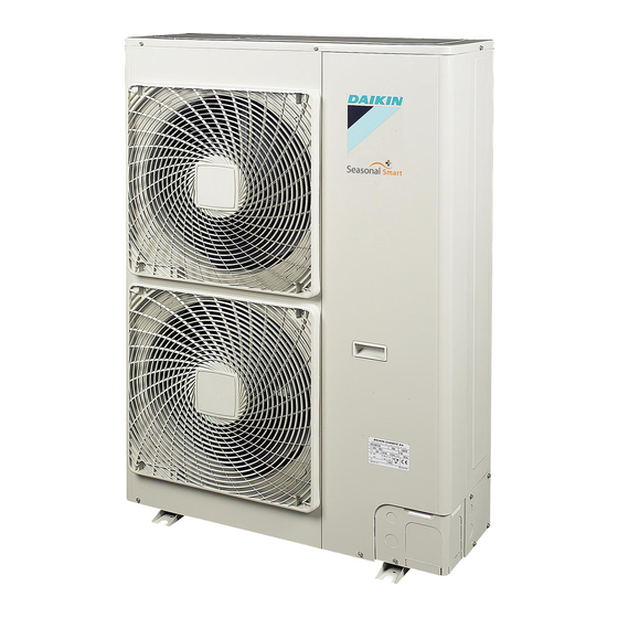
Daikin RZQG71L8Y1L Installation Manual
Split system air conditioners
Hide thumbs
Also See for RZQG71L8Y1L:
- Installation manual (16 pages) ,
- Installer's reference manual (32 pages)
Summary of Contents for Daikin RZQG71L8Y1L
- Page 1 Installation manual Split system air conditioners RZQG71L9V1L RZQG71L8Y1L RZQG100L8Y1L Installation manual RZQG125L8Y1L English Split system air conditioners RZQG140L7Y1L...
- Page 2 (mm) — ≥100 A, B, C — ≥100 ≥100 ≥100 B, E — ≥100 ≥1000 ≤500 A, B, C, E — ≥150 ≥150 ≥150 ≥1000 ≤500 — ≥500 D, E — ≥500 ≥1000 ≤500 B, D <H >H ≥100 ≥500 ≥500 >H <H...
-
Page 3: Table Of Contents
Specifications of standard wiring components.... Daikin website (publicly accessible). 4.5.3 To connect the electrical wiring on the outdoor unit..▪ The full set of latest technical data is available on the Daikin Finishing the outdoor unit installation ........extranet (authentication required). 4.6.1 To finish the outdoor unit installation ...... -
Page 4: Preparation
3 Preparation 4.1.2 To install the outdoor unit Preparation Preparing installation site 3.1.1 Installation site requirements of the outdoor unit Mind the spacing guidelines. See the "Technical data" chapter, and the figures on the inside of the front cover. 4× M12 INFORMATION The sound pressure level is less than 70 dBA. -
Page 5: To Prevent The Outdoor Unit From Falling Over
4 Installation Snow 3 If you have chosen the downwards piping route: In regions with snowfall, snow might build up and freeze between the ▪ Drill (a, 4×) and remove the knockout hole (b). heat exchanger and the external plate. This might decrease the ▪... -
Page 6: To Determine If Oil Traps Are Required
4 Installation WARNING Checking the refrigerant piping Provide adequate measures to prevent that the unit can be used as a shelter by small animals. Small animals that 4.3.1 Checking refrigerant piping: Setup make contact with electrical parts can cause malfunctions, smoke or fire. -
Page 7: Charging Refrigerant
4 Installation 4.4.3 Charging refrigerant: Setup Charging refrigerant "4.3.1 Checking refrigerant piping: Setup" on page 6. 4.4.1 To determine the additional refrigerant amount 4.4.4 To charge refrigerant To determine if adding additional refrigerant is necessary WARNING Then ▪ Only use R410A as refrigerant. Other substances may cause explosions and accidents. -
Page 8: Connecting The Electrical Wiring
4 Installation 4.5.3 To connect the electrical wiring on the Connecting the electrical wiring outdoor unit DANGER: RISK OF ELECTROCUTION NOTICE ▪ Follow the wiring diagram (delivered with the unit, WARNING located at the inside of the service cover). ALWAYS use multicore cable for power supply cables. ▪... -
Page 9: Finishing The Outdoor Unit Installation
4 Installation 4 Route the wiring through the frame and connect it to it. Finishing the outdoor unit installation Routing through Choose one of the 3 possibilities: the frame 4.6.1 To finish the outdoor unit installation 1 Insulate and fix the refrigerant piping and interconnection cable as follows: a Power supply cable Gas pipe... -
Page 10: Commissioning
5 Commissioning Commissioning To perform a test run This task is only applicable when using the BRC1E52 user interface. NOTICE ▪ When using BRC1E51, see the installation manual of the user NEVER operate the unit without thermistors and/or interface. pressure sensors/switches. Burning of the compressor might result. -
Page 11: Error Codes When Performing A Test Run
5 Commissioning 3 Check operation for 3 minutes. Error codes when performing a 4 Check operation of the airflow direction. test run Action Result If the installation of the outdoor unit has NOT been done correctly, Press. the following error codes may be displayed on the user interface: Air Volume/direction Air Volume Direction... -
Page 12: Technical Data
6 Technical data Technical data A subset of the latest technical data is available on the regional Daikin website (publicly accessible). The full set of latest technical data is available on the Daikin extranet (authentication required). Service space: Outdoor unit Suction side In the illustrations below, the service space at the suction side is based on 35°C DB and cooling operation. -
Page 13: Wiring Diagram: Outdoor Unit
6 Technical data Wiring diagram: Outdoor unit The wiring diagram is delivered with the unit, located at the inside of Motor (lower fan) the service cover. Switching power supply Notes for RZQG_V1: Q1DI Earth leakage circuit breaker (field supply) R1~R6 Resistor Symbols (see legend). - Page 16 4P473073-1 2017.03...


Need help?
Do you have a question about the RZQG71L8Y1L and is the answer not in the manual?
Questions and answers