
Subscribe to Our Youtube Channel
Related Manuals for DRAKE DTD1000A


Summary of Contents for DRAKE DTD1000A
- Page 1 DTD1000A Demodulator Module 8VSB/QAM INSTRUCTION MANUAL Model Item # Description DTD1000A 1002512A Demodulator Module 8VSB/QAM 937-746-4556 www.rldrake.com © 2016 R.L. Drake Holdings, LLC. Rev: 030916 / 651228700A...
- Page 2 We recommend that you write the following information in the spaces provided below. Purchase Location Name: Purchase Location Telephone Number: DTD1000A Serial Number: This product incorporates copyright protection technology that is protected by U.S. patents and other intellectual property rights. Reverse engineering or disassembly is prohibited.
-
Page 3: Table Of Contents
Table of Contents CAUTION STATEMENTS ................................. 4 IMPORTANT SAFETY INSTRUCTIONS ..........................4 GENERAL DESCRIPTION & FEATURES ..........................6 SPECIFICATIONS ..................................6 INSTALLATION & POWER-UP ..............................7 OPERATION: MEQ1000B ................................ 8 MODULE TAB ..................................9 OPERATION: MEQ1000/A ..............................10 HEADEND CONTROL PROGRAM ........................... 10 SERVICE .................................... -
Page 4: Caution Statements
Important Safety Instructions 1. Read Instructions—All the safety and operating instructions should be read before the product, be sure the antenna or cable system is grounded so as to provide some protection product is operated. against voltage surges and built-up static charges. Article 810 of the National Electrical Code, ANSI/NFPA 70, provides information with regard to proper grounding of the mast and sup- 2. - Page 5 Importantes De Sécurité 1. Lire les directives—Toutes les directives de sécurité et d’utilisation devraient être lues aux électrodes de mise à la terre et les spécifications pour les électrodes de mise à la terre. avant de mettre l’appareil en opération. Voir la figure A.
-
Page 6: General Description & Features
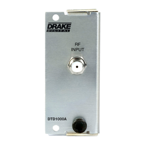
General Description and Features INTRODUCTION The Drake® DTD1000A Demodulator Module (in tandem with the Drake® MEQ1000A/B Multiplexing Hybrid QAM Modulator) is designed to provide a demodulated transport stream from a ATSC 8VSB or QAM annex B RF signal.. The MEQ1000A/B accepts transport streams from up to two input modules. -
Page 7: Installation & Power-Up
SDM1000 Satellite Demodulator, or the SDE24A, HDE24A, and SDI24A Encoder Modules: 1. Ensure power to the MEQ1000 is off. 2. Gently slide the DTD1000A Demodulator Input Module into one of the open input module bays in the rear of the MEQ1000. -
Page 8: Operation: Meq1000B
Operation : MEQ1000B The DTD1000A Demodulator Module may be used as a input module for the MEQ1000, MEQ1000A or MEQ1000B. When used in a MEQ1000B: Power on the chassis. When viewed from the rear panel, the leftmost slot is slot 1 and slot 2 to the right. Open a web browser on your computer and enter the following URL address (http://172.16.80.1). -
Page 9: Module Tab
Module Tab DTD1000A Demodulator Module Tab Select Module: Indicates module installed in Slot 1 or Slot 2. Module Information: Indicates Module Type, Software Version, and Firmware Revision. Tuner Lock: Lock or Unlocked. AGC Lock: Lock or uUnlocked. Demodulator Lock: Lock or Unlocked. -
Page 10: Operation: Meq1000/A
1. Unit ID: # (0 thru 63) • Assign a unique ID # from 1 to 63 to each MEQ1000A in order to distinguish them for remote access from the Drake. • ID # 0 allows front panel access only. - Page 11 Headend Control Program (continued) Once connected launch the Drake Digital Headend Control Program the following screen will appear. (See Fig. 2) Figure 2 Alternatively, the MEQ1000/A with DTD1000A Demodulator Module or other input modules may be programmed and monitored using the Drake Digital Headend Control Program. The Headend Control Program is shipped with MEQ1000/A or available for download at http://tinyurl.com/28o5f4d.
- Page 12 Headend Control Program (continued) Select MEQ1000 tab and check box corresponding to ID # programmed from front panel. Select “View/Edit”. Figure 4 Select Input A or Input B tab corresponding to the location of the DTD1000. Settings are entered in the left hand column and the DTD1000 current settings are displayed in the right hand column.
- Page 13 Notes: www.rldrake.com 937.746.4556 |...
-
Page 14: Service
Please perform whatever steps are applicable from the product’s Instruction Manual before calling or writing as this could save unnecessary phone charges. Please do not return the product without calling Drake Service and following the steps above first;... -
Page 15: Warranty
Blonder Tongue Laboratories, Inc. Limited Warranty Limited Warranty Blonder Tongue Laboratories, Inc. (BT) will at its sole option, either repair or replace (with a new or factory reconditioned product, Seller will at its sole option, either repair or replace (with a new or factory reconditioned product, as Seller may determin e) any product manufactured or sold (or in as BT may determine) any product manufactured by BT which proves to be defective in materials or workmanship or fails to Blonder Tongue Laboratories, Inc. - Page 16 R.L. DRAKE HOLDINGS, LLC Sales: 937-746-4556 • Support: 937-746-6990 • Fax: 937-806-1510 www.rldrake.com...
Need help?
Do you have a question about the DTD1000A and is the answer not in the manual?
Questions and answers