DRAKE VMM 600, VMM 860 - Video Modulator System Manual
- Instruction manual (2 pages) ,
- Quick manual (2 pages) ,
- Manual (2 pages)
Advertisement
INTRODUCTION
The R.L. Drake VMM 600/VMM 860 Video Modulator System is a professional quality modular headend system designed to optimize rack space. Up to 12 VMM 600 and/or VMM 860 modulators can be racked alongside a single power supply in the Drake 12 position rack mount or up to 4 modulators can be racked in the 4 position rack mount. Either model is a high quality, fixed channel heterodyne audio/ video modulator.
The VMM 600 provides a modulated visual and RF carrier output on any single VHF channel 2-13; Lowband channel A8; Midband channel A-I and A5-A1; Superband channel J-W; Hyperband channel AA-ZZ and AAA-XXX (CATV 63-86) or UHF channel 14-35.
Aeronautical channels are offset positive with a tolerance of ±5 kHz as required by FCC rules.
The VMM 860 provides a modulated visual and RF carrier output on any single Hyperband channel 87-135 or UHF channel 36-69.
The heterodyne conversion system, in conjunction with the use of a SAW filter, insures optimum vestigial selectivity for adjacent channel headends.
The modulators are designed to accept any standard audio/video source such as NTSC video and audio baseband signals from a satellite receiver, TV camera, videotape recorder, TV demodulator, or similar signal source.
The modulators accept standard (sync negative) polarity video at a 0.7 to 2.5 Vp-p level. All level controls are located on the front panel for ease of operation. Output level of +45 dBmV is typical and is adjustable from +30 to +45 dBmV.
Field-defeatable audio pre-emphasis enables passing of BTSC encoded standard baseband stereo audio signals. The Drake model MMTS20 stereo encoder may be used with the VMM when stereo audio is required.
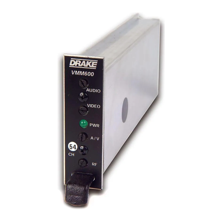
FRONT PANEL DESCRIPTION

F1 - AUDIO Level Control
The setting of this screwdriver adjustment determines the peak aural carrier deviation. Clockwise rotation increases the carrier deviation.
F2 - VIDEO Level Control
The setting of this screwdriver adjustment determines the video modulation level. Clockwise rotation increases the modulation depth.
F3 - POWER Indicator
Lights when the unit is connected to the required source of DC power via the rear panel DC INPUT connector.
F4 - A/V Ratio Control
This screwdriver adjustment varies the level of the aural carrier over a range from 12 to 19 dB below the visual carrier. The aural carrier should be adjusted to approximately 15 dB below the visual carrier (normal operation). Clockwise rotation increases the aural carrier level and thus decreases the A/V ratio.
F5 - "CH#" (Channel)
The modulator is factory aligned to the channel number indicated.
F6 - RF Output Level
This screwdriver adjustment permits decreasing the RF output level approximately 12 dB below its specified output level as the control is rotated counterclockwise. The maximum output level is set with the adjustment fully clockwise.
REAR PANEL DESCRIPTION

R1 - VIDEO INPUT Connector
This is the baseband video input to the IF circuits. This input accepts baseband input thru 4.2 MHz video at levels from 0.7 Vp-p to 1.5 Vp-p.
R2 - AUDIO INPUT Connector
This is an unbalanced audio input to the IF circuits. This "RCA" (phono) connector input accepts baseband thru 15 kHz audio at a nominal level of 250 mV RMS (approximately 0 dBm). NOTE: An externally accessible test point jumper defeats the audio pre-emphasis for stereo capability.

R3 - DC INPUT Connector
This 3-pin connector (Male) accepts the appropriate mating DC power cable. Observe proper orientation and wiring.
R4 - RF OUTPUT Connector
This is the modulator output.
INSTALLATION
CONNECTIONS AND CONTROLS
All connections to and from each modulator are made through the rear panel. Figure below illustrates an installation with 12 modulator units combined through a passive signal combiner. Additional channels can be added by using additional VMM 600 or VMM 860 modulators and either multi-port combiners or combinations of two-port combiners.

INSTALLATION NOTES
Level adjustment provides optimum performance in multi-channel installations. The modulator outputs should be checked periodically with a spectrum analyzer to maintain a ±1 dB variation of adjacent channel carriers.
Aural/Visual (A/V) ratios should be held to -15 dB or less. The output 'RF' and 'A/V (Ratio)' controls are used respectively to make these adjustments.
RACK MOUNTING
Adequate ventilation is very important in multi-channel installations. Units should be spaced apart by at least one panel height wherever possible, and some air movement is advisable in enclosed rack cabinets. Excessive heat will shorten component life and modulator performance will be degraded without proper cooling.

R.L. DRAKE COMPANY
230 INDUSTRIAL DRIVE
FRANKLIN, OHIO 45005 U.S.A.
CUSTOMER SERVICE AND PARTS TELEPHONE:
+1 (937) 746-6990
TELEFAX:
+1 (937) 806-1576
WORLD WIDE WEB SITE: http://www.rldrake.com

Documents / Resources
References
Download manual
Here you can download full pdf version of manual, it may contain additional safety instructions, warranty information, FCC rules, etc.
Download DRAKE VMM 600, VMM 860 - Video Modulator System Manual
Advertisement


Need help?
Do you have a question about the VMM 600 and is the answer not in the manual?
Questions and answers