Table of Contents
Advertisement
Quick Links
Advertisement
Table of Contents

Related Manuals for LORD MicroStrain 3DM-GX5-25


Summary of Contents for LORD MicroStrain 3DM-GX5-25
- Page 1 LORD User Manual ® -GX5-25 Attitude and Heading Reference System (AHRS)
- Page 2 ® MicroStrain Sensing Systems 459 Hurricane Lane Suite 102 Williston, VT 05495 United States of America Phone: 802-862-6629 www.microstrain.com sensing_support@LORD.com sensing_sales@LORD.com Copyright © 2017 LORD Corporation ® ® ® ® ™ ® ® ® ® ® , 3DM-DH , 3DM-DH3...
-
Page 3: Table Of Contents
® -GX5-25 User Manual Table of Contents System Family Overview Sensor Overview 2.1 Components 2.2 Interface and Indicators Basic Setup and Operations 3.1 Software Installation 3.2 System Connections 3.3 Software Interface 3.3.1 Interactive Help Menu 3.4 Sensor Communication 3.5 Satellite Link 3.6 Sensor Settings 3.6.1 Saving Configurations 3.7 Data Monitoring and Recording... - Page 4 ® -GX5-25 User Manual 5.2 Tare Mounting Pitch-Roll 5.3 Magnetometer Auto Calibration 5.3.1 Enable 5.3.2 Capture 5.4 Magnetometer Manual Calibration 5.5 Estimation Filter Aiding 5.6 Heading Aiding Settings 5.6.1 Bias Convergence 5.7 Adaptive Anomaly Rejection 5.7.1 Gravity Adaptive 5.7.2 Mag Adaptive 5.8 Communications Bandwidth 5.9 Platform Frame Transformation 5.10 Estimation Filter Operation...
- Page 5 ® -GX5-25 User Manual 7.2 Sensor Wiring 7.3 Sampling on Start-up 7.4 Connecting to a Datalogger 7.5 Using Wireless Adapters Troubleshooting 8.1 Troubleshooting Guide 8.2 Repair and Calibration 8.3 Maintenance 8.4 Technical Support Parts and Configurations 9.1 Standard Configurations 9.2 Accessories 9.3 Sales Support Specifications Reference Diagrams...
-
Page 6: System Family Overview
The LORD Sensing MIP Data Communications Protocol (DCP) that is used to communicate with LORD Sensing inertial sensors is also available for users who want to develop customized software solutions. Because of the unified set of commands across the sensor family, it is easy to migrate code from one inertial sensor to another. -
Page 7: Sensor Overview
Sensor measurements and computed outputs can be viewed and recorded with the LORD Sensing MIP Monitor software that is available as a free download from the LORD Sensing website. Alternatively, users can write custom software with the LORD Sensing open source data communication protocol. The data is time-aligned and available by either polling or continuous stream. -
Page 8: Components
For a complete list of available configurations, accessories, additional system products, and ordering information, see Parts and Configurations on page 59 . LORD Sensing Item Description Model Part Number... -
Page 9: Interface And Indicators
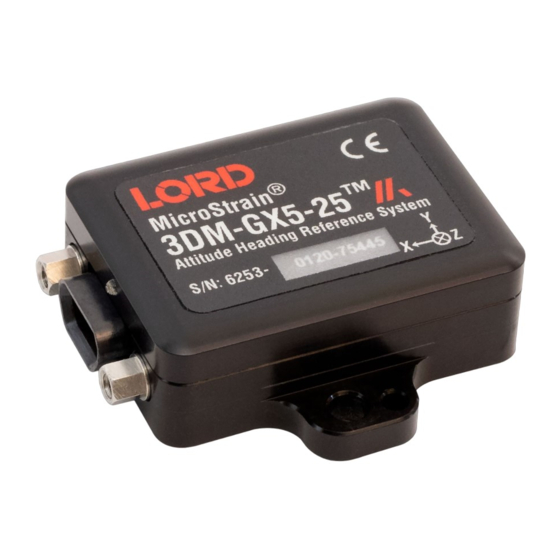
® -GX5-25 User Manual 2.2 Interface and Indicators The 3DM-GX5-25 sensor interface includes a communications and power input connector. The sensor is installed using the mounting and alignment holes as needed ( see Sensor Mounting on page 1 The indicators on the 3DM-GX5-25 include a device status indicator and the device information label. The table below describes the basic status indicator behavior. -
Page 10: Basic Setup And Operations
Users may also utilize the LORD Sensing MIP Data Communications Protocol (DCP) to write custom software applications with expanded or specific feature sets needed for the application. -
Page 11: Software Installation
® -GX5-25 User Manual 3.1 Software Installation NOTE The MIP Monitor Software Suite includes hardware drivers required for 3DM-GX5-25 sensor operation. Sensors will not be recognized without these drivers installed. To Install the MIP Monitor software on the host computer, complete the following steps: 1. -
Page 12: System Connections
Once power is applied the sensor is on and active ( Specifications on page 62 To acquire sensor data the following components are needed: 3DM-GX5-25 sensor, communication cable, power cable (as applicable for RS232 communications) , and a host computer with LORD Sensing MIP Monitor installed. Figure 5 -System Connections... -
Page 13: Software Interface
® -GX5-25 User Manual 3.3 Software Interface The MIP Monitor software includes a main window with system information and menus, a device settings window, and several data monitoring windows. The main window provides an overview of connected devices. Devices are selected by clicking on them. -
Page 14: Sensor Communication
® -GX5-25 User Manual 3.4 Sensor Communication Once power has been applied to the sensor, it is functional. The sensor selects the appropriate serial communication (USB or RS232) on power-up based on which cable is connected. If the hardware drivers have been installed, communication can be established using the MIP Monitor software interface. -
Page 15: Satellite Link
® -GX5-25 User Manual Satellite Link 3.6 Sensor Settings Device settings are stored in the sensor memory. Only the configuration options available for the sensor being used are displayed in the menus. To enter the settings menu, either right-click on the sensor name highlighted in the main window, and then select Device Settings, or select Settings >... -
Page 16: Saving Configurations
® -GX5-25 User Manual 3.6.1 Saving Configurations Sensor settings are saved temporarily by selecting the OK button in the Device Setup window after configuration, but they are lost when the device is powered off. To save current settings, so they are automatically restored the next time the device is powered on, select Settings >... -
Page 17: Data Monitoring And Recording
® -GX5-25 User Manual 3.7 Data Monitoring and Recording Throughout the MIP Monitor views the same icons are used to control data streaming (sampling) and recording. These icons can be found in the MIP Monitor main window icon toolbar and in each data monitoring window. -
Page 18: View Recorded Data
® -GX5-25 User Manual Figure 12 - Data Streaming is an example of Sensor Data Monitoring, which displays the selected IMU/AHRS measurements. In data monitoring windows, no data will be displayed until data streaming is started, and no data will be recorded (even if it is being viewed) until data recording is initiated (armed). - Page 19 CSV files can be viewed with Microsoft Excel, Quattro Pro, Open Office, or other CSV editors and spreadsheet programs. Data recorded in Binary format requires a translation program utilizing the LORD Sensing MIP Data Communications Protocol (DCP) to make it user-readable.
- Page 20 ® -GX5-25 User Manual 4. To end recording press the Arm Recording button again, and select OK in the confirmation prompt window. 5. Select the Stop Streaming icon to end sampling. 6. Use the red "X" in the upper right of the sensor monitoring window to exit monitoring mode.
-
Page 21: Sensor Measurements
® -GX5-25 User Manual Sensor Measurements The 3DM- GX5 - 25 block diagram ( Figure 14 - 3DM- GX5- 25 Block Diagram ) describes its primary hardware components and internal configuration. Integrated Micro-Electro-Mechanical System (MEMS) sensors within the 3DM- GX5- 25 are collectively known as the Inertial Measurement Unit (IMU) and include tri-axial gyroscopes (gyros), tri-axial accelerometers, tri-axial magnetometers, and a pressure altimeter. -
Page 22: Direct Sensor Measurements (Imu Outputs)
® -GX5-25 User Manual 4.1 Direct Sensor Measurements (IMU Outputs) The sensors in an Inertial Navigation System (INS), from which measurements for navigation and orientation are obtained, are collectively known as the Inertial Measurement Unit (IMU). These sensors are arranged on the three primary axes (x, y, and z) to sense angular rate, acceleration, and the local magnetic field. - Page 23 The Complementary Filter (CF) attitude, and up and north vector outputs are computed estimations ® from the LORD Sensing 3DM-GX3 inertial sensor family and are available to maintain backwards compatibility. For new applications it is recommended that these estimations be computed with the...
-
Page 24: Computed Outputs
® -GX5-25 User Manual 4.2 Computed Outputs (Estimation Filter) The computed outputs are measurements from the 3DM- GX5- 25 IMU sensors that are blended through an Auto-Adaptive Extended Kalman Filter (EKF) algorithm. The Kalman Filter produces a better estimation of attitude and heading (AHRS) outputs than can be achieved by the inertial sensors individually. - Page 25 ® -GX5-25 User Manual To view and record Estimation outputs, see Basic Setup and Operations on page 10 Measurement Units Description indicates the current state of the EF, such Filter Status as running or initializing GPS time corresponding to the calculated fil- GPS Time weeks &...
-
Page 26: Sensor Reference Frames
® -GX5-25 User Manual 4.3 Sensor Reference Frames 4.3.1 Geodetic Frame The World Geodetic System is the standard for cartography and navigation. The latest revision, WGS84, is the reference coordinate system for GPS. It also calculates the magnitude of the local gravity vector using the WGS84 reference formulas. -
Page 27: North East Down (Ned) Frame
® -GX5-25 User Manual 4.3.2 North East Down (NED) Frame The North-East-Down (NED) frame is a local coordinate frame, which is formed by a tangent plane located at a particular point (current coordinates) on the WGS84 reference ellipse. The NED frame is constructed with the (true) North vector along the line of longitude, the East vector along the line of latitude, and the Down vector normal to and towards the tangent plane ( Figure 18 - North East... -
Page 28: Sensor Frame
® -GX5-25 User Manual 4.3.3 Sensor Frame The sensor frame is indicated on the top of the device and is oriented such that the x-axis vector is parallel with the long side of the sensor and points toward the sensor connector, the y-axis is 90° to the right of the x-axis, and the z-axis goes through the bottom of the sensor (outward). -
Page 29: Platform Frame
® -GX5-25 User Manual 4.3.4 Platform Frame The 3DM-GX5-25 includes the option to define an orientation transformationand offset distance from the sensor frame to a user-definable platform frame. This is useful when the sensor cannot be mounted in the same location or orientation as the desired reference point on the platform frame. The transformation from sensor to platform frame is defined with Euler angles and is expressed as a rotation from the sensor frame to the platform frame. - Page 30 ® -GX5-25 User Manual In the MIP Monitor software the transformation setting s are entered at: Settings > Device > Figure 21 - Platform Frame Settings Estimation Filter > Mounting in the field ( ). To tare pitch-roll, Tare Mounting Pitch-Roll on page 32 Figure 21 -Platform Frame Settings The orientation transformation affects the following EF outputs: attitude, position, linear and compensated acceleration, compensated angular rate, and gravity vector.
-
Page 31: Performance Optimization
® -GX5-25 User Manual Performance Optimization 5.1 Gyroscope Bias Gyroscope biases (offsets) can be zeroed out to set a baseline value for the static home position and conditions in the application. This should be done after sensor installation. To set the gyroscope baseline, place the sensor or sensor platform in the desired home position. Allow 2-3 minutes for the sensor to warm up and for the temperature to stabilize for the best bias capture. -
Page 32: Tare Mounting Pitch-Roll
This function captures the current pitch-roll orientation of the device and sets it as the level reference, providing a convenient way to set the sensor to vehicle frame transformation. For more information on the corresponding LORD Sensing MIP Data Communications Protocol (DCP) command, see the DCP Manual . -
Page 33: Magnetometer Auto Calibration
® -GX5-25 User Manual 5.3 Magnetometer Auto Calibration 5.3.1 Enable Enabling the EF Mag Hard Iron Auto Calibration allows estimation of the magnetometer bias (bias tracking) for purposes of auto- calibration. Enabling the EF Mag Soft Auto Calibration allows estimation of the magnetometer scale factor (scale factor tracking) for purposes of auto-calibration. To enable, select the sensor name in the MIP Monitor software main window, then select Settings >... -
Page 34: Capture
These maneuvers are necessary to establish the magnetometer offset and scale factors. For more information on the corresponding LORD Sensing MIP Data Communications Protocol (DCP) command, see the DCP Manual . -
Page 35: Magnetometer Manual Calibration
To mitigate this effect when using the 3DM-GX5-25 magnetometer to aid in heading estimations, a field calibration of the magnetometer after final installation is highly recommended. This can be accomplished using LORD Sensing MIP Hard and Soft Iron Calibration software. The following are instructions for field calibrating the magnetometers: 1. - Page 36 ® -GX5-25 User Manual 3. The sensor should automatically appear in the sensor list. If not, use the Refresh button Figure 26 - Sensor Menu to query it and then select the sensor ( ). 4. Select the Arm Recording button next to Collect Data. The software will begin taking readings, as indicated by the points counter in the graphing window.
- Page 37 ® -GX5-25 User Manual not likely not be rotated on all three axis. Ellipsoid Fit is generally a better correction when soft iron effects are present but only if enough data points can be collected in all quadrants. If the range of motion is restricted in one dimension, the Spherical Fit may be the best choice.
-
Page 38: Estimation Filter Aiding
® -GX5-25 User Manual 5.5 Estimation Filter Aiding There are two categories to customize heading and pitch-roll. To enter the Estimation Filter Aiding menu, select the sensor name in the MIP Monitor software main window, then select Settings > Device > Estimation Filter > EF Aiding. 1. -
Page 39: Heading Aiding Settings
The external heading message setting means the heading is derived from one of two possible external messages provided by the user: 1. (0x0D, 0x17) or 2. (0x0D, 0x1F) in the LORD Sensing MIP Data Communications Protocol (DCP) DCP Manual. -
Page 40: Bias Convergence
® -GX5-25 User Manual 5.6.1 Bias Convergence Accurate estimation of the biases can take several minutes to converge, therefore after the filter is initialized, the free-inertial performance will continue to improve until the bias estimations settles. The MEMS sensor manufacturers quote bias drift stability numbers which correspond to the expected drift in bias while the sensor is operating. -
Page 41: Mag Adaptive
® -GX5-25 User Manual 5.7.2 Mag Adaptive Enabling this feature will allow the filter to reject magnetometer readings when the magnitude error exceeds the high limit (in m/s ^ 2). The bandwidth (in Hz) sets the cutoff frequency of the low pass see Communications Bandwidth on page 42 filter applied to the magnetometer error ( ). -
Page 42: Communications Bandwidth
® -GX5-25 User Manual 5.8 Communications Bandwidth When selecting sensor and estimation outputs to be recorded, communication bandwidth considerations should be taken into account, especially when using RS232 serial communications. Lower baud rates equate to lower communication bandwidth, which can be consumed quickly by selecting a large number of measurements at high sample rates. -
Page 43: Estimation Filter Convergence
® -GX5-25 User Manual The 3DM-GX5-25 runs an Auto-Adaptive Extended Kalman Filter as a full-state dynamics model. The state propagation utilizes Newton’s and Euler’s equations of motion with the acceleration and angular rate treated as control inputs. The Kalman filter estimates the full state of attitude for a total of 16 states: 4 attitude (quaternion), 3 gyro bias, 3 magnetometer bias, and 6 magnetometer scale-factor states. -
Page 44: Vibration Isolation
The import and export settings features provide a consolidated file of the user settings, enabling Device Settings information to be saved and shared. For example, exporting settings to the LORD technical support team helps facilitate fast and accurate resolution of technical issues. - Page 45 ® -GX5-25 User Manual Figure 33 -Import/Export Settings Menu...
-
Page 46: Sensor Installation
® -GX5-25 User Manual Sensor Installation 6.1 Sensor Mounting The 3DM - GX5 - 25 sensor housing is rated for indoor use only, unless used inside a protective enclosure. The sensor has two mounting tabs with holes for fastening. Mounting screws should be brass or 300 Series stainless steel. -
Page 47: Oem System Integration
Select 3DM- GX5- 25 from the "Select a Product to View Documentation" drop- down menu. The manual will appear in a list under "General Documentation." The MIP software developers kit (SDK) includes sample code and can be found on the LORD Sensing see Technical Support on page 58 website Support page or by contacting Technical Support ( The LORD Sensing MIP Data Communications Protocol (DCP) describes each command description,... -
Page 48: Packet Builder
When in Sensor Direct mode the device normal functionality is not available. The protocol commands used to interface with the IMU are a subset of the standard LORD Sensing MIP Data Communications Protocol (DCP) and are further described in the LORD Sensing MIP Data... - Page 49 ® -GX5-25 User Manual Communications Protocol (DCP) manual. For additional information contact LORD Sensing see Technical Support on page 58 Technical Support ( To enter this mode select Advanced > Communications> Sensor Direct from the MIP Monitor main Figure 36 - window.
-
Page 50: Sensor Wiring
Connect only one at a time. Observe connection polarity. Sensor power and serial communications cables are available from LORD Sensing and come with the sensor connectivity kits. These cables will have the micro-DB9 connector on one end (to connect to the sensor) and either a standard DB9 on the other end (for RS232 communication) or a USB connector (for USB communications). -
Page 51: Sampling On Start-Up
MIP Monitor for data logging is not required. This functionality can also be embedded in user- designed applications by using the corresponding LORD Sensing MIP Data Communications Protocol (DCP) command. To view or download the DCP Manual, go to: http://www.microstrain.com/support/documentation, from the drop-down menu select 3DM-GX5-... -
Page 52: Connecting To A Datalogger
Many inertial applications incorporate dataloggers of all different types to collect and distribute sensor outputs. For more information and examples refer to the "Using Dataloggers with Inertial Sensors" Technical Note on the LORD Sensing website, or contact LORD Sensing Technical Support ( Technical Support on page 58 7.5 Using Wireless Adapters... -
Page 53: Troubleshooting
® -GX5-25 User Manual Troubleshooting 8.1 Troubleshooting Guide... - Page 54 NOTE: if the baud rate is set higher than the computer serial port is capable of reading, communication will be permanently lost with the device. To recover, it will need to be connected to a higher speed port, connected via USB cable, or sent to LORD...
- Page 55 If no conclusion can be determined, or to send a device in for repair, contact LORD Sensing Technical Support ( See Technical Support on page 3.1 sampling settings are incorrect...
- Page 56 ® -GX5-25 User Manual Problem Possible cause and recommended solution conditions outside of its operating specifications.
-
Page 57: Repair And Calibration
LORD Sensing model number and serial number, as well as your name, organization, shipping address, telephone number, and email. Normal turn- around for RMA items is seven days from receipt of item by LORD Sensing . Warranty Repairs LORD Sensing warrants its products to be free from defective material and workmanship for a period of one (1) year from the original date of purchase. -
Page 58: Technical Support
-GX5-25 User Manual 8.4 Technical Support There are many resources for product support found on the LORD Sensing website including technical notes, FAQs, and product manuals. http://www.microstrain.com/support_overview.aspx For further assistance our technical support engineers are available to help with technical and applications questions. -
Page 59: Parts And Configurations
User Manual Parts and Configurations 9.1 Standard Configurations For the most current product information, custom, and OEM options not listed below, refer to the LORD Sensing website or contact the LORD Sensing Sales Department. Table 4 - Model Numbers describes the standard models available at the time this manual was published. - Page 60 ® -GX5-25 User Manual The same options are available in each model, and are indicated in the last four digits of the product part number. For a list of the starter kit contents,( see Components on page 1 Figure 39 -Standard Part Numbers...
-
Page 61: Accessories
Table 6 - Sensor Mating Connector 9.3 Sales Support Products can be ordered directly from the LORD Sensing website by navigating to the product page and using the Buy feature. http://www.microstrain.com/inertial For further assistance, our sales team is available to help with product selection, ordering options, and questions. -
Page 62: Specifications
® -GX5-25 User Manual Specifications General Triaxial accelerometer, triaxial gyroscope, triaxial Integrated magnetometer, pressure altimeter, and temperature sensors sensors, Inertial Measurement Unit (IMU) outputs: acceleration, angular rate, magnetic field , ambient pressure, Delta-theta, Delta-velocity Computed outputs: Extended Kalman Filter (EKF): filter status, timestamp, attitude estimates (in Euler angles, quaternion, orientation Data outputs matrix), linear and compensated acceleration, bias... - Page 63 ® -GX5-25 User Manual Computed Outputs EKF outputs: ±0.25° RMS roll and pitch, ±0.8° RMS heading (typ) Attitude accuracy CF outputs: ±0.5° RMS roll and pitch, ±1.5° RMS heading (typ) Attitude heading range 360° about all axes Attitude resolution < 0.01° Attitude repeatability 0.2°...
-
Page 64: Reference Diagrams
The diagrams in this section are to intended to aid in product installation and troubleshooting. For more see Technical Support on page 58 information contact LORD Sensing Technical Support ( 11.1 Sensor Dimensions and Origin This diagram describes the sensor physical specification including the measurement point of origin. -
Page 65: Power Supply Specifications
® -GX5-25 User Manual 11.2 Power Supply Specifications These specifications describe the power supply included in the 3DM-GX5-25 connectivity kit. Operating Parameters AC input voltage rating 100 to 240 V ac AC input voltage range 90 to 264 V ac AC input frequency range 47 to 63 Hz (RMS) maximum @ 120 V ac... -
Page 66: Communication And Power Cables
® -GX5-25 User Manual 11.3 Communication and Power Cables These diagrams describe the cables included in the 3DM-GX5-25 connectivity kits. Only one is included in each kit, depending on the type of kit ordered. Figure 41 -RS232 Communications and power cable Figure 42 -USB Communications cable... - Page 67 ® -GX5-25 User Manual Figure 43 -Connecter interface cable (sold separately, PN: 6224-0100)
-
Page 68: Reference Documents
-GX5-25 User Manual Reference Documents Many references are available on the LORD Sensing website including product user manuals, technical notes, and quick start guides. These documents are continuously updated and may provide more accurate information than printed or file copies. ... -
Page 69: Glossary
® -GX5-25 User Manual Glossary A/D Value The digital representation of analog voltages in an analog-to-digital (A/D) conversion. The accuracy of the conversion is dependent on the resolution of the system electronics. Higher resolution produces a more accurate conversion. Acceleration In physics,acceleration is the change in the rate of speed (velocity) of an object over time. - Page 70 ® -GX5-25 User Manual ASTM (Association of Standards and Testing) a nationally accepted organization for the testing and calibration of technological devices Attitude the orientaion of an object in space with reference to a defined frame, such as the North-East-Down (NED) frame Azimuth A horizontal arc measured between a fixed point (such as true north) and the vertical circle passing...
- Page 71 ® -GX5-25 User Manual Delta-Theta the time integral of angular rate expressed with refernce to the device local coordinate system, in units of radians Delta-velocity the time integral of velocity expressed with refernce to the device local coordinate system, in units of g*second where g is the standard gravitational constant ECEF (Earth Centered Earth Fixed) a reference frame that is fixed to the earth at the center of the earth and turning about earth's axis in the...
- Page 72 ® -GX5-25 User Manual Host (computer) The host computer is the computer that orchestrates command and control of attached devices or net- works. Inertial Measurement System Inclinometer device used to measure tilt, or tilt and roll Inertial pertaining to systems that have inertia or are used to measure changes in inertia as in angular or linear accelerations INS (Inertial Navigation System) systems that use inertial measurements exclusively to determine position, velocity, and attitude, given...
- Page 73 ® -GX5-25 User Manual NED (North-East-Down) A geographic reference system acronym for Original Equipment Manufacturer Offset A non-zero output signal of a sensor when no load is applied to it, typically due to sensor imperfections. Also called bias. Orientation The orientaion of an object in space with reference to a defined frame. Also called attitude. Pitch In navigation pitch is what occurs when vertical force is applied at a distance forward or aft from the cen- ter of gravity of the platform, causing it to move up or down with respect to the sensor or platform frame...
- Page 74 ® -GX5-25 User Manual acronym for Root Mean Squared Roll In navigation roll is what occurs when a horizontal force is applied at a distance right or left from the cen- ter of gravity of the platform, causing it to move side to side with respect to the sensor or platform frame origin.
- Page 75 ® -GX5-25 User Manual UTC (Coordinated Universal Time) The primary time standard for world clocks and time. It is similar to Greenwich Mean Time (GMT). Vector a measurement with direction and magnitude with refernce from one point in space to another Velocity The rate of change of position with respect to time.
Need help?
Do you have a question about the MicroStrain 3DM-GX5-25 and is the answer not in the manual?
Questions and answers