Advertisement
Quick Links
LORD QUICK START GUIDE
®
V-Link
-200
Wireless 8 Channel Analog Input Sensor Node
The V- Link - 200 wireless sensor node features eight analog input channels
designed to accommodate a wide range of Wheatstone bridge and analog
sensors, including strain, load cell, torque, pressure, acceleration, vibration,
magnetic field, displacement, and geophones. There are four channels for single-
ended sensor measurement, four channels for differential sensor measurement,
and an on-board internal temperature sensor.
To acquire sensor data, the V- Link- 200 is used with a LORD Sensing data
gateway such as the WSDA-101 or WSDA-1500 Base. V-Link-200 sensor nodes
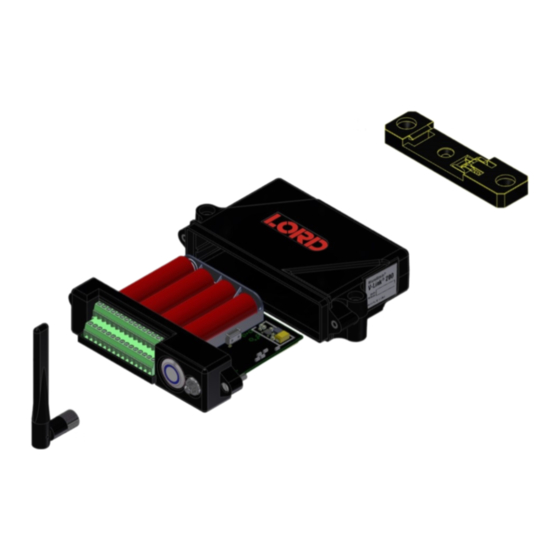
come with the following components.
Item
Description
A
V-Link-200
B
Antenna with right angle adapter
C
Node tester board
AA Lithium batteries (3.6 V dc, 2.4
D
Ah)
DIN rail clip
E
#6-32 x 3/8" Thread forming screws
Wireless Simplicity, Hardwired Reliability™
The V-Link-200 LEDs indicate operational modes showing when the node
is booting up, idle and waiting for a command, sampling, resynchronizing,
or if there is an error.
Quantity
1
1
1
indicator
4
1
3
Figure 1 - Interface and Indicators
Indicator
Behavior
OFF
Rapid green flashing
on start-up
1 (slow) green pulse
Device
per second
status
1 green blink every 2
seconds
Blue LED during
sampling
Red LED
Node Status
Node is OFF
Node is booting up
Node is idle and waiting
for a command
Node is sampling
Node is resynchronizing
Error or low battery
Advertisement

Related Manuals for LORD V-Link-200


Summary of Contents for LORD V-Link-200
- Page 1 To acquire sensor data, the V- Link- 200 is used with a LORD Sensing data gateway such as the WSDA-101 or WSDA-1500 Base. V-Link-200 sensor nodes come with the following components.
-
Page 2: System Operation
Sensor nodes have three operational modes: active , sleep , and idle . When the hardware. Access the free software download on the LORD Sensing website at: node is sampling, it is in active mode. When sampling stops, the node is switched into idle mode, which is used for configuring node settings, and allows toggling between sampling and sleeping modes. - Page 3 If the base and node are on the same operating frequency, the node will 2. Open the SensorConnect software. populate below the Base Station listing when powering on the V-Link-200. 3. The gateway should appear in the Controller window automatically with a communication port assignment.
- Page 4 ® V-Link -200 Wireless Sensor Node Quick Start Guide B. Add Node Manually If the node failed to be added, a failure message will appear. This means the node did not respond to the base station which could indicate the Adding a node manually requires entering the node address and its node is not in idle mode or it may be on another frequency.
- Page 5 SensorConnect. The configuration menus show the channels and configuration options available for the type of node being used. For this example the V-Link-200 tester board is on channel 1. Figure 12 - Node Configuration Menu 1. Select Hardware > Input Range for channel 1, select +/-2 mV from 6.
- Page 6 ® V-Link -200 Wireless Sensor Node Quick Start Guide Figure 15 - Half-Bridge * Figure 13 - Channel Settings 9. When the calibration is complete, the Wireless Node Configuration window will appear. 10. Select Apply Configuration to write to node memory. See below for wiring of other strain gauges.
- Page 7 ® V-Link -200 Wireless Sensor Node Quick Start Guide 6. Configure Sampling Setting and Start Data Acquisition 1. Left click on the Base Station > Sampling, and indicate the nodes to be sampled by checking the box to the left of each node. 2.
- Page 8 200. battery or the node in the trash. Follow proper battery disposal protocol, or contact LORD Sensing Technical 2. It is important to replace all four of the batteries at the same time, Support for information on extracting the battery or observing the correct polarity orientation.
Need help?
Do you have a question about the V-Link-200 and is the answer not in the manual?
Questions and answers