
Subscribe to Our Youtube Channel
Related Manuals for Icom IC-F6121D-51B


Summary of Contents for Icom IC-F6121D-51B
- Page 1 INSTRUCTION MANUAL VHF MOBILE TRANSCEIVERS iF5120D Series UHF MOBILE TRANSCEIVERS iF6120D Series...
-
Page 2: Explicit Definitions
Equipment damage may occur. If disregarded, inconvenience only. No risk NOTE of personal injury, fire or electric shock. CAUTION: Changes or modifications to this transceiver, not expressly approved by Icom Inc., could void your au- thority to operate this transceiver under FCC regulations. -
Page 3: Precautions
Other microphones Icom, Icom Inc. and the Icom logo are registered trademarks of Icom have different pin assignments and may damage the trans- Incorporated (Japan) in Japan, the United States, the United King- ceiver. -
Page 4: Table Of Contents
TABLE OF CONTENTS IMPORTANT ................i 3 CONNECTION AND MAINTENANCE ....15–17 EXPLICIT DEFINITIONS ............i ■ Rear panel connection ..........15 FCC INFORMATION ............. i ■ Supplied Accessories ..........16 PRECAUTIONS ..............ii ■ Mounting the transceiver ..........16 TABLE OF CONTENTS ............iii ■... -
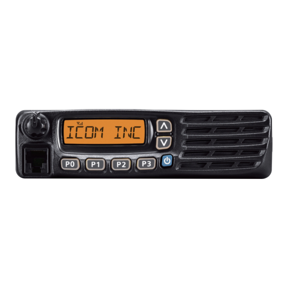
Page 5: Panel Description
PANEL DESCRIPTION ■ Front panel Function display (p. 2) Speaker q AF VOLUME CONTROL KNOB [VOL] t MICROPHONE CONNECTOR Rotate the knob to adjust the audio output level. Connect the supplied or optional microphone. • Minimum audio level is pre-programmed. (p. 12) NEVER connect non-specified microphones. -
Page 6: Function Display
PANEL DESCRIPTION ■ Function display y ENCRYPTION ICON Appears when the encryption function is activated while operating in the digital mode. u BELL ICON Appears/blinks when a matching 2/5-tone or Digital ID* is received, depending on the preprogramming. i SCAN ICON ➥... -
Page 7: Programmable Function Keys
[P0], [P1], [P2] and [P3] programmable function keys. • When a scan is started with the Power ON Scan or Automatic Consult your Icom dealer or system operator for details con- scan function, push this key to cancel it. The cancelled scan cerning your transceivers programming. - Page 8 PANEL DESCRIPTION ■ Programmable function keys (Continued) LOCK KEY PRIO A/B KEYS ➥ Hold down this key until “LOCK ON” is displayed to elec- ➥ Push to select the Priority A or Priority B channel. tronically lock all programmable keys except the follow- ➥...
- Page 9 PANEL DESCRIPTION TONE/RAN CH SELECT KEY WIDE/NARROW KEY ➥ While in analog mode, push to enter the continuous tone Push to toggle the IF bandwidth between wide and narrow. channel selection mode. Then push [CH Up] or [CH Down] • The wide passband width can be selected from 25.0 or 20.0 kHz using the CS-F3100D/F5120D .
- Page 10 PANEL DESCRIPTION ■ Programmable function keys (Continued) TX CODE CHANNEL SELECT KEY CALL KEYS ➥ Push to enter the TX code channel selection mode, then Push to transmit a 2/5-tone ID code. push [CH Up] or [CH Down] to set a desired channel. •...
- Page 11 PANEL DESCRIPTION USER SET MODE KEY Ext. CH Sel Mode KEY ➥ Hold down for 1 second to enter the User Set mode. Push to turn the Ext. CH Select function ON or OFF. • While in the User Set mode, push this key to select an item*, When the function is turned ON, memory channels can be and change the value or setting using [CH Up] or [CH Down].
-
Page 12: Basic Operation
BASIC OPERATION ■ Turning ON the power ■ Channel selection q Push [ ] to turn ON the power. There are several methods to select channels, and they may w If the transceiver is programmed for a start up password, differ, depending on your system set up. -
Page 13: Call Procedure
BASIC OPERATION ■ Call procedure ■ Receiving and transmitting Receiving: When your system employs tone signaling (excluding CTCSS and DTCS), a call procedure may be necessary prior to voice q Hold down [ ] for 1 second to turn ON the power. transmission. - Page 14 BASIC OPERATION ■ Receiving and transmitting (Continued) D TX code channel selection D Transmitting notes If the transceiver has a key assigned to [TX Code CH Select], • Transmit inhibit function the display can be toggled between the operating channel The transceiver has several inhibit functions which restrict number (or name) and TX code channel number (or name).
- Page 15 BASIC OPERATION D TX code number edit (PMR operation only) USING [TX CODE ENTER] KEY: If the transceiver has a key assigned to [TX Code CH Select] q Push [TX Code Enter] to enter the TX code edit mode. or [TX Code Enter], TX code contents can be edited within the allowable digits.
-
Page 16: User Set Mode
BASIC OPERATION ■ User Set mode ■ Stun function The User Set mode allows you to set seldom-changed set- The dispatcher can send a 2/5-tone signal that will stun, kill tings, and you can “customize” the transceiver operation to or revive your transceiver. suit your preferences and operating style. -
Page 17: Emergency Transmission
BASIC OPERATION ■ Emergency transmission D NOTES When [Emergency] is held down for the specified time pe- Depending on the preprogramming, the following functions riod*, the emergency signal is transmitted on the specified are automatically activated. Ask your dealer for details. emergency channel once or repeatedly. -
Page 18: Power Off Emergency Function
BASIC OPERATION ■ Power OFF Emergency function ■ Priority A channel selection When the transceiver has a key assigned to Power OFF When one of the following operations is performed, the trans- Emergency, you can use the function. ceiver automatically selects the Priority A channel. This function makes the transceiver transmit emergency •... -
Page 19: Connection And Maintenance
CONNECTION AND MAINTENANCE ■ Rear panel connection q ANTENNA CONNECTOR e MICROPHONE HANGER Antenna Connect to an antenna. Ask your Connect the supplied micro- dealer about antenna selection phone hanger to the vehicle’s ground for microphone ON/OFF and placement. hook functions. (See page 1) w EXTERNAL SPEAKER JACK Connect to a 4 to 8 ø... -
Page 20: Supplied Accessories
CONNECTION AND MAINTENANCE ■ Supplied Accessories ■ Mounting the transceiver The universal mounting bracket supplied with your trans- Microphone Microphone hanger Microphone ceiver allows overhead mounting. and screw set hanger cable • Mount the transceiver securely with the 4 supplied screws to a thick surface which can support more than 1.5 kg (3.3 lb). -
Page 21: Antenna
Icom transceiver. soft, dry cloth. Icom is not responsible for the destruction or damage to an Icom DO NOT use harsh solvents such as benzine or transceiver in the event the Icom transceiver is used with equipment alcohol, as they will damage the transceiver sur- that is not manufactured or approved by Icom. -
Page 22: Safety Training Information
SAFETY TRAINING INFORMATION 3. IC-F5121D: Your Icom radio generates RF electromagnetic en- Transmit only when people outside the vehicle are at least the ergy during transmit mode. This radio is designed recommended minimum distance of 100 centimeters away from for and classified as “Occupational Use Only”, the properly installed antenna. - Page 23 LCD. You can cause the radio to transmit by pressing the “PTT” switch. Electromagnetic Interference/Compatibility During transmissions, your Icom radio generates RF energy that can possibly cause interference with other devices or systems. To avoid such interference, turn OFF the radio in areas where signs are posted to do so.
- Page 24 SAFETY TRAINING INFORMATION 3. IC-F5121D: Votre radio Icom produit une énergie électro- Émettre uniquement lorsque les personnes à l’extérieur du véhi- magnétique de radiofréquences (RF), en mode cule se trouvent à au moins la distance minimale recommandée de transmission. Cette radio est conçue pour de 100 cm de l’antenne correctement installée.
- Page 25 Interférence électromagnétique et compatibilité Afin de vous assurer que votre exposition à En mode de transmission, votre radio Icom produit de l’énergie de une énergie électromagnétique de RF se situe RF qui peut provoquer des interférences avec d’autres appareils ou dans les limites permises par la FCC pour une systèmes.
- Page 26 MEMO...
- Page 27 MEMO...
- Page 28 A-6903H-1EX-e Printed in Japan © 2010–2012 Icom Inc. 1-1-32 Kamiminami, Hirano-ku, Osaka 547-0003, Japan Printed on recycled paper with soy ink.
Need help?
Do you have a question about the IC-F6121D-51B and is the answer not in the manual?
Questions and answers