
Related Manuals for G.M. International D1014S

Summary of Contents for G.M. International D1014S
- Page 1 D1014S - D1014D INSTRUCTION & SAFETY MANUAL SIL 2 Repeater Power Supply Hart compatible DIN-Rail Models D1014S, D1014D D1014 - SIL 2 Repeater Power Supply Hart compatible ISM0052-16...
-
Page 2: Technical Data
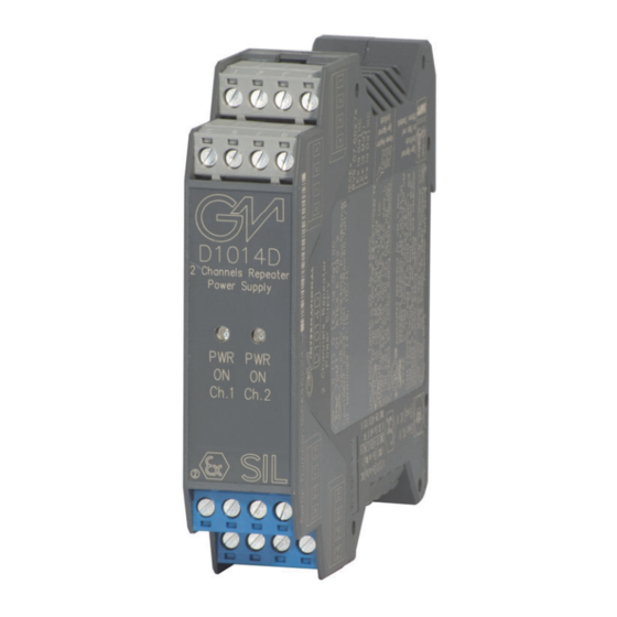
Characteristics General Description: The single and dual channel DIN Rail Repeater Power Supply, D1014S and D1014D is a high integrity analog input interface suitable for applications requiring SIL 2 level (according to IEC61508:2010 Ed. 2) in safety related system for high risk industries. Provides a fully floating dc supply for energizing conventional 2 wires 4-20 mA transmitters located in Hazardous Area, and repeats the current in floating circuit to drive a Safe Area load. -
Page 3: Hazardous Area
Voltage Source mode or - Output Ch 2 for Current Sink mode - Input Ch 1 for 2 wire Transmitters + Ch 2 Power Supply 12-24 Vdc Not used - Ch 2 Power Supply 12-24 Vdc G.M. International ISM0052-16 D1014 - SIL 2 Repeater Power Supply Hart compatible... -
Page 4: Parameters Table
For Division 1 and Zone 0 installations, the configuration of Intrinsically Safe Equipment must be FM approved under Entity Concept (or third party approved); for Division 2 installations, the configuration of Intrinsically Safe Equipment must be FM approved under non-incendive field wiring or Entity Concept (or third party approved). D1014 - SIL 2 Repeater Power Supply Hart compatible G.M. International ISM0052-16... -
Page 5: Function Diagram
In 1 8 - Ch.2 Supply 12-24 Vdc Out 2 2 Wire Tx Source I Source V Sink I In 2 MODEL D1014S Ch.1 Supply 12-24 Vdc Out 1 2 Wire Tx Source I Source V Sink I In 1 G.M. - Page 6 The 2 channels of D1014D module could be used to increase the hardware fault tolerance, needed for a higher SIL of a certain Safety Function, as they are they are completely independent each other, not containing common components. In fact, the analysis results got for D1014S (single channel) are also valid for each channel of D1014D (double channel).
- Page 7 Failure to properly installation or use of the equipment may risk to damage the unit or severe personal injury. The unit cannot be repaired by the end user and must be returned to the manufacturer or his authorized representative. Any unauthorized modification must be avoided. G.M. International ISM0052-16 D1014 - SIL 2 Repeater Power Supply Hart compatible...
-
Page 8: Operation
On the section “Function Diagram” and enclosure side a block diagram identifies all connections and configuration DIP switches. Identify the number of channels of the specific card (e.g. D1014S is a single channel model and D1014D is a dual channel model), the function and location of each connection terminal using the wiring diagram on the corresponding section, as an example: Connect 12-24 Vdc power supply positive at terminal “3”... - Page 9 1 x 0.5 mm Span Trimmer Turn the trimmer clockwise to Increase Output value or turn the trimmer counterclockwise Zero Trimmer if you want to decrease Output value. G.M. International ISM0052-16 D1014 - SIL 2 Repeater Power Supply Hart compatible...
- Page 10 Cut both pins of the connector to open the wiring between the terminals, using a wire cutter D1014 - SIL 2 Repeater Power Supply Hart compatible G.M. International ISM0052-16...
- Page 11 DC supply 30 V range at terminals 14 (+) and 15 (-), the multimeter (DMM) for the reading in DC supply 20 mA range at terminals 1 (+) and 2 (-). Execute the next test to verify D1014S unit channel or execute it twice to verified both D1014D unit channels. If the power ON Leds are off, check supply voltage, polarity and wiring.
Need help?
Do you have a question about the D1014S and is the answer not in the manual?
Questions and answers