Advertisement
Quick Links
INSTRUCTION MANUAL
MECHATROLINK I/O MODULE
(NPN/PNP discrete input & NPN transistor output, 16 points each,
MIL connector, MECHATROLINK- III use)
BEFORE USE ....
Thank you for choosing M-System. Before use, please check
contents of the package you received as outlined below.
If you have any problems or questions with the product,
please contact M-System's Sales Office or representatives.
■ PACKAGE INCLUDES:
Discrete I/O module ............................................................(1)
DIN rail mounter slider ......................................................(2)
■ MODEL NO.
Confirm Model No. marking on the product to be exactly
what you ordered.
■ INSTRUCTION MANUAL
This manual describes necessary points of caution when
you use this product, including installation, connection and
basic maintenance procedures.
5-2-55, Minamitsumori, Nishinari-ku, Osaka 557-0063 JAPAN
Phone: +81(6)6659-8201 Fax: +81(6)6659-8510 E-mail: info@m-system.co.jp
MODEL
POINTS OF CAUTION
■ CONFORMITY WITH EU DIRECTIVES
• The equipment must be mounted inside the instrument
panel of a metal enclosure.
• The actual installation environments such as panel con-
figurations, connected devices, connected wires, may af-
fect the protection level of this unit when it is integrated
in a panel system. The user may have to review the CE
requirements in regard to the whole system and employ
additional protective measures to ensure the CE conform-
ity.
■ POWER INPUT RATING & OPERATIONAL RANGE
• Locate the power input rating marked on the product and
confirm its operational range as indicated below:
24V DC rating: 24V ±10%, approx. 100mA
■ GENERAL PRECAUTIONS
• Before you remove the unit or mount it, turn off the power
supply and I/O signal for safety.
• Before you remove the terminal block and MIL connector
or mount it, make sure to turn off the power supply and
I/O signal for safety.
• DO NOT set the switches on the module while the power
is supplied. The switches are used only for maintenance
without the power.
■ ENVIRONMENT
• Indoor use.
• When heavy dust or metal particles are present in the
air, install the unit inside proper housing with sufficient
ventilation.
• Do not install the unit where it is subjected to continuous
vibration. Do not subject the unit to physical impact.
• Environmental temperature must be within -10 to +55°C
(14 to 131°F) with relative humidity within 30 to 90% RH
in order to ensure adequate life span and operation.
• With vertical mounting, for heat dissipation leave at least
10 mm (.39 in.) at the both side of the unit.
■ WIRING
• Do not install cables close to noise sources (relay drive
cable, high frequency line, etc.).
• Do not bind these cables together with those in which
noises are present. Do not install them in the same duct.
■ AND ....
• The unit is designed to function as soon as power is sup-
plied, however, a warm up for 10 minutes is required for
satisfying complete performance described in the data
sheet.
R7F4HML3-D-DAC32A
EM-8002-A Rev.2 P. 1 / 12
Advertisement

Related Manuals for M-system R7F4HML3-D-DAC32A


Summary of Contents for M-system R7F4HML3-D-DAC32A
- Page 1 MIL connector, MECHATROLINK- III use) BEFORE USE ..POINTS OF CAUTION Thank you for choosing M-System. Before use, please check ■ CONFORMITY WITH EU DIRECTIVES contents of the package you received as outlined below. • The equipment must be mounted inside the instrument If you have any problems or questions with the product, panel of a metal enclosure.
-
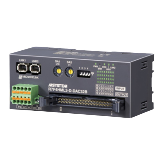
Page 2: Component Identification
LED green indicators shows the signal status. ON : LED ON OFF : LED OFF Station Address Setting (LSD) Station Address Setting (MSD) EM-8002-A Rev.2 P. 2 / 12 5-2-55, Minamitsumori, Nishinari-ku, Osaka 557-0063 JAPAN Phone: +81(6)6659-8201 Fax: +81(6)6659-8510 E-mail: info@m-system.co.jp... - Page 3 X12 INPUT 12 INPUT 4 X11 INPUT 11 INPUT 3 X10 INPUT 10 INPUT 2 INPUT 9 INPUT 1 INPUT 8 INPUT 0 EM-8002-A Rev.2 P. 3 / 12 5-2-55, Minamitsumori, Nishinari-ku, Osaka 557-0063 JAPAN Phone: +81(6)6659-8201 Fax: +81(6)6659-8510 E-mail: info@m-system.co.jp...
-
Page 4: Mounting Instructions
2) Set the upper hook at the rear side of the unit on the DIN rail. 3) Push in the lower. Note: leave at least 10 mm (.39 in.) at the both side of the unit. EM-8002-A Rev.2 P. 4 / 12 5-2-55, Minamitsumori, Nishinari-ku, Osaka 557-0063 JAPAN Phone: +81(6)6659-8201 Fax: +81(6)6659-8510 E-mail: info@m-system.co.jp... -
Page 5: Terminal Connections
115 (4.53) 55 (2.17) DIN RAIL 35mm wide [4 (.16)] 2 - 4.3 dia. 4 deep (2 - 1.17 dia. 0.16 deep) EM-8002-A Rev.2 P. 5 / 12 5-2-55, Minamitsumori, Nishinari-ku, Osaka 557-0063 JAPAN Phone: +81(6)6659-8201 Fax: +81(6)6659-8510 E-mail: info@m-system.co.jp... -
Page 6: Mounting Requirements
• PNP Connection − • NPN Connection 24V DC − Output Connection Examples − *1. The network cable can be connected to either one. EM-8002-A Rev.2 P. 6 / 12 5-2-55, Minamitsumori, Nishinari-ku, Osaka 557-0063 JAPAN Phone: +81(6)6659-8201 Fax: +81(6)6659-8510 E-mail: info@m-system.co.jp... - Page 7 Not used CMD_CTRL CMD_STAT Refer to CMD_CTRL/CMD_STAT. Recalculation of parameters and set up. Other than 00H is not supported. ≥ 5 Reserve EM-8002-A Rev.2 P. 7 / 12 5-2-55, Minamitsumori, Nishinari-ku, Osaka 557-0063 JAPAN Phone: +81(6)6659-8201 Fax: +81(6)6659-8510 E-mail: info@m-system.co.jp...
- Page 8 • DISCONNECT (0FH) Stops communication with master station. BYTE COMMAND RESPONSE REMARKS DISCONNECT (0FH) DISCONNECT (0FH) Release connection command ≥ 1 Reserve EM-8002-A Rev.2 P. 8 / 12 5-2-55, Minamitsumori, Nishinari-ku, Osaka 557-0063 JAPAN Phone: +81(6)6659-8201 Fax: +81(6)6659-8510 E-mail: info@m-system.co.jp...
- Page 9 Not used CH3 IN LO CH3 data low 8 bits Not used CH3 IN HI CH3 data high 8 bits Not used EM-8002-A Rev.2 P. 9 / 12 5-2-55, Minamitsumori, Nishinari-ku, Osaka 557-0063 JAPAN Phone: +81(6)6659-8201 Fax: +81(6)6659-8510 E-mail: info@m-system.co.jp...
- Page 10 Alarm 8: FCS error, 9: Command data not received, A: Synchronous frame not received, B: Synchronization time interval error, C: WDT error EM-8002-A Rev.2 P. 10 / 12 5-2-55, Minamitsumori, Nishinari-ku, Osaka 557-0063 JAPAN Phone: +81(6)6659-8201 Fax: +81(6)6659-8510 E-mail: info@m-system.co.jp...
- Page 11 Sub Device 1 Version ---- Sub Device 2 Name ---- Sub Device 2 Version ---- Sub Device 3 Name ---- Sub Device 3 Version ---- EM-8002-A Rev.2 P. 11 / 12 5-2-55, Minamitsumori, Nishinari-ku, Osaka 557-0063 JAPAN Phone: +81(6)6659-8201 Fax: +81(6)6659-8510 E-mail: info@m-system.co.jp...
- Page 12 Output 2 Input 3 Output 3 Input 7 Output 7 Input 8 Output 8 Input 15 Output 15 0: OFF 1: ON EM-8002-A Rev.2 P. 12 / 12 5-2-55, Minamitsumori, Nishinari-ku, Osaka 557-0063 JAPAN Phone: +81(6)6659-8201 Fax: +81(6)6659-8510 E-mail: info@m-system.co.jp...
Need help?
Do you have a question about the R7F4HML3-D-DAC32A and is the answer not in the manual?
Questions and answers