
Related Manuals for LRS TX-7471-C232


Summary of Contents for LRS TX-7471-C232
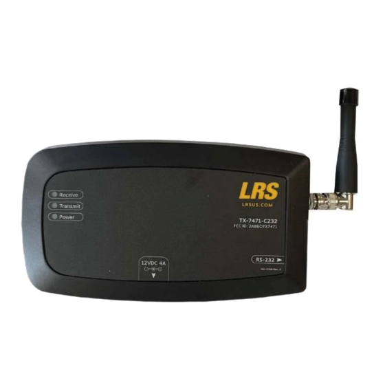
- Page 1 U S E R M A N U A L TX-7471-C232 Paging System Transmitter Long Range Systems, LLC. LRSUS.COM | 800.437.4996 | 214.553.5308 XU-0157 Rev. A...
-
Page 2: Table Of Contents
TABLE OF CONTENTS Installation and Setup ..................................2 Set Restaurant ID ..................................4 Repeat Delay ..................................... 5 High Power Setting .................................. 5 Positioning and Installing the Repeater ........................... 6 Service Questions and Answers ................................. 7 Warranty ......................................7 FCC Statement ..................................... 8 Terms &... -
Page 3: Installation And Setup
INSTALLATION AND SETUP Basic Installation 1) Connect the antenna 2) Plug the 12V power supply into the side of the Transmitter. 3) Connect the serial cable from the connector on the Transmitter to the serial port on the host computer. 4) Note the COM Port that the serial cable is connected to on the host computer. -
Page 4: Set Restaurant Id
Set Restaurant ID This must be set correctly to page pagers. To set the Restaurant ID, type RID,x and press ENTER twice. X is the Restaurant ID. Example: To set an ID of 2, type RID,2 and press ENTER twice. Example Restaurant ID to 2 HyperTerminal Output Showing ID as 2 Type STAT and press ENTER... -
Page 5: Repeat Delay
Repeat Delay To turn ON Repeat Delay, type RPTDLY,1 and press ENTER twice. To turn OFF Repeat Delay, type RPTDLY,0 and press ENTER twice. Example Repeat Delay ON Status View Showing Repeat Delay ON High Power Setting To change the Power Setting, type HWPR,x and press ENTER twice. X is the Power Setting, a value of 0 to 4. -
Page 6: Positioning And Installing The Repeater
POSITIONING AND INSTALLING THE REPEATER Note: The best place to mount your repeater is on a ceiling or wall that is very high. The idea is to get the signal as high as possible so it “umbrellas” the guest and thus all pagers can receive it. The repeater operates at its best when installed at the “fringe”... -
Page 7: Service Questions And Answers
Call Long Range Systems at 800.437.4996 or 214.553.5308 to place your order. Loss Deterrent and Recovery Return address labels on the back of all of your equipment are highly recommended. Should any of your pagers be taken off premise, this will help them find their way back to you. You may order return address labels from LRS or print them yourself. Power Over Connector Previous hardware revisions of the T7471-C232 would deliver 5 VDC on pin 9 of the DE-9 serial connector. -
Page 8: Fcc Statement
FEDERAL COMMUNICATIONS COMMISSION INTERFERENCE STATEMENT 1. This device complies with Part 15 of the FCC Rules. Operation is subject to the following two conditions: (1) This device may not cause harmful interference. (2) This device must accept any interference received, including interference that may cause undesired opera- tion. -
Page 9: Terms & Conditions
Purchaser hereby grants to LRS a royalty-free, perpetual, irrevocable license to use and distribute this data and results obtained through Purchaser’s use of the Deliverables for any and all purposes; provided that LRS shall not identify any Purchaser, or distribute to third parties any “protected health information” (as defined by HIPAA) or billing or financial payment data of any customer or consumer of Purchaser, without the express prior consent of such Purchaser. - Page 10 Deliverable or for any other breach of any of its duties and obligations to Purchaser shall be lim- ited to the amount of money that was paid for the defective Deliverable or the other duty or obligation. LRS will in no event be liable for any lost profit or any other type of consequential damage.
- Page 11 General Terms and Conditions, any agreement that incorporates them, or any of the Deliverables. These General Terms and Conditions, and any agreement that incorporates them, may not be modified or superseded, except by a written agreement or a written amendment that is signed by LRS. In the event of any inconsistency between these General Terms and Conditions or any agreement that incorporates them and any form or other document...
Need help?
Do you have a question about the TX-7471-C232 and is the answer not in the manual?
Questions and answers