
Related Manuals for King Canada KC-15CM

Summary of Contents for King Canada KC-15CM
- Page 1 3.5 CUBIC FEET PORTABLE CEMENT MIXER MODEL: KC-15CM INSTRUCTION MANUAL COPYRIGHT © 2020 ALL RIGHTS RESERVED BY KING CANADA TOOLS INC.
-
Page 2: Warranty Information
Please keep your dated proof of purchase for warranty and servicing purposes. REPLACEMENT PARTS Replacement parts for this product are available at our authorized King Canada service centers across Canada. Please use the 10 digit part numbers listed in this manual for all part orders where applicable. - Page 3 GENERAL & SPECIFIC SAFETY INSTRUCTIONS VOLTAGE WARNING: Before connecting the tool to a power source (receptacle, outlet, etc.) be sure the voltage supplied is the same as that specified on the nameplate of the tool. A power source with voltage greater than that for the specified tool can result in SERIOUS INJURY to the user - as well as damage to the tool.
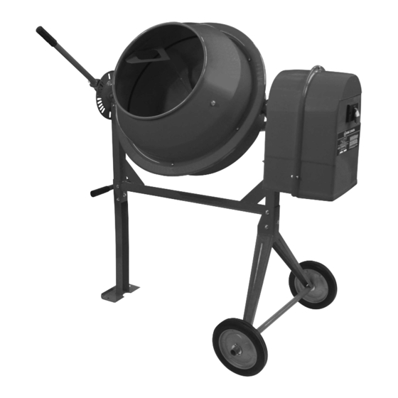
- Page 4 3. Tilting lever angle control plate 9. Motor housing & cover 4. Lifting handle (1 of 2) 10. Upper drum 5. Frame 11. Mixing paddle (1 of 2) 6. Lower drum MODEL KC-15CM Drum capacity 3.5 cu.ft. Drum opening 15” Drum speed 32 RPM Motor...
-
Page 5: Electrical Information
ELECTRICAL INFORMATION WARNING! ALL ELECTRICAL CONNECTIONS MUST BE DONE BY A QUALIFIED ELECTRICIAN. FAILURE TO COMPLY MAY RESULT IN SERIOUS INJURY! ALL ADJUSTMENTS OR REPAIRS MUST BE DONE WITH THE CEMENT MIXER DISCONNECTED FROM THE POWER SOURCE. FAILURE TO COMPLY MAY RESULT IN SERIOUS INJURY! POWER SUPPLY 120V GROUNDED OUTLET CURRANT... - Page 6 ASSEMBLY UNPACKING Due to modern mass production techniques, it is unlikely that your King Canada cement mixer is faulty or that a part is missing. If you find anything wrong, do not operate until the parts have been replaced or the fault has been rectified. Failure to do so could result in serious personal injury.
- Page 7 ASSEMBLY Assembling Tilt Lever 1. Install the tilting lever angle control plate (A) Fig.7 to the support bracket shaft (B) using 2 short hex. bolts, washers and flange hex. nuts (C). FIGURE 7 2. In order to install the tilting lever assembly, first locate the tilting lever (A) Fig.8 and loosen the hex.
- Page 8 ASSEMBLY Assembling V-belt 1. Position the V-Belt (A) Fig.11 around the motor pulley (B) and then over the drum pulley (C). It may be neccessary to lift the motor plate in order to place V-belt around the pulleys. Then push the motor inward until it is directly under the drum pulley. Tighten the motor hardware to secure the motor.
-
Page 9: Assembly And Operation
ASSEMBLY & OPERATION Assembling Drum Gasket & Upper Drum Cover 1. Place the rubber gasket (A) Fig.15 onto the lower drum (B) as shown. Line up the rubber gasket mounting holes with the ones on the lower drum. It is recommended to use a gasket sealer (not included) to fix the rubber gasket to the lower drum. -
Page 10: Maintenance And Troubleshooting
See Electrical Information section. PARTS DIAGRAM & PARTS LISTS Refer to the Parts section of the King Canada web site for the most updated parts diagram and parts list.
Need help?
Do you have a question about the KC-15CM and is the answer not in the manual?
Questions and answers