Table of Contents
Advertisement
Quick Links
Inverter HF-520 Option
PROFIBUS-DP
Installation Manual
Type: SI-P3/V-H
NOTICE
1. Make sure that this installation manual is delivered to
the end user of inverter unit.
2. Read this manual before installing or operating the
inverter unit, and store it in a safe place for
reference.
Manual
No.DM2309E-1
Advertisement
Table of Contents

Related Manuals for Sumitomo Drive Technologies HF-520


Summary of Contents for Sumitomo Drive Technologies HF-520
- Page 1 Inverter HF-520 Option PROFIBUS-DP Installation Manual Type: SI-P3/V-H NOTICE 1. Make sure that this installation manual is delivered to the end user of inverter unit. 2. Read this manual before installing or operating the inverter unit, and store it in a safe place for reference.
- Page 2 Copyright © 2015 Sumitomo Heavy Industries, LTD. All rights reserved. No part of this publication may be reproduced, stored in a retrieval system, or transmitted, in any form, or by any means, mechanical, electronic, photocopying, recording, or otherwise, without the prior written permission of Sumitomo. No patent liability is assumed with respect to the use of the information contained herein.
-
Page 3: Table Of Contents
Table of Contents 1 PREFACE AND SAFETY ......4 2 PRODUCT OVERVIEW ......10 3 RECEIVING . -
Page 4: Preface And Safety
1 Preface and Safety Preface and Safety Sumitomo manufactures products used as components in a wide variety of industrial systems and equipment. The selection and application of Sumitomo products remain the responsibility of the equipment manufacturer or end user. Sumitomo accepts no responsibility for the way its products are incorporated into the final system design. - Page 5 Applicable Documentation The following manuals are available for the PROFIBUS-DP Option: Option Unit Inverter Read this manual first. HF-520 Series Option The installation manual is packaged with the PROFIBUS-DP Installation Manual PROFIBUS-DP Option and contains a basic overview Manual No.: DM2309E of wiring, settings, functions, and fault diagnoses.
- Page 6 HF-520 http//www.shi.co.jp/ptc/ Freq Reference (Hz) FWD / REV Sel (Hz) Output Freq Output Current Selected Monitor HF-520 Operating and Maintenance Manual Monitor Verify SetUpGuide Parameter Set Auto-Tuning Manual No. : DM2301E WARNING Risk of electric shock. Read manual before installing.
- Page 7 1 Preface and Safety ◆ Registered Trademarks • PROFIBUS-DP is a registered trademark of PROFIBUS International. • Other company names and product names listed in this manual are registered trademarks of those companies. ◆ Supplemental Safety Information Read and understand this manual before installing, operating, or servicing this option unit. The option unit must be installed according to this manual and local codes.
- Page 8 1 Preface and Safety General Safety ■ General Precautions • The diagrams in this section may include option units and drives without covers or safety shields to illustrate details. Be sure to reinstall covers or shields before operating any devices. The option board should be used according to the instructions described in this manual.
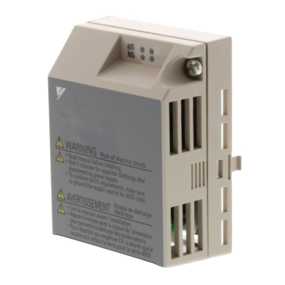
- Page 9 1 Preface and Safety Option Unit Label Warnings ■ Warning information is displayed on the option unit as shown in the figure below. Follow all warnings and safety instructions when using the product. Figure 1 WARNING Risk of electric shock. Read manual before installing.
-
Page 10: Product Overview
2 Product Overview Product Overview ◆ About This Product PROFIBUS is an open digital communication system supporting a wide range of fast, time- critical applications. PROFIBUS-DP (Decentral Periphery) is one of the three PROFIBUS variants. DP is dedicated to fast data communication between systems and peripherals at a field level. This PROFIBUS-DP Option connects a drive to a field network using the PROFIBUS-DP protocol. -
Page 11: Receiving
3 Receiving Receiving Please perform the following tasks after receiving the PROFIBUS-DP Option: • Inspect the PROFIBUS-DP Option for damage. • Verify receipt of the correct model by checking the information on the nameplate (see Figure • If you receive the wrong model or the PROFIBUS-DP Option does not function properly, contact your supplier. -
Page 12: Profibus-Dp Option Components
4 PROFIBUS-DP Option Components PROFIBUS-DP Option Components ◆ PROFIBUS-DP Option Figure 2 PROFIBUS-DP with cover removed PROFIBUS-DP with cover attached Underside COMM A – LED (Comm: green) H – Nameplate B – LED (BF: red) I – Function Earth cable connection (FE) C –... - Page 13 4 PROFIBUS-DP Option Components ◆ Dimensions The installed PROFIBUS-DP Option adds 27 mm (1.06 in.) to the total depth of the drive. (Figure Figure 3 27 mm (1.06 in.) Figure 3 Dimensions...
- Page 14 4 PROFIBUS-DP Option Components ◆ Communication connector The drive has a 9 pin D-sub connector for installing the option card. Once installed, the drive can connect to a PROFIBUS network. Figure 4 Figure 4 Communication connector location Table 2 Communication connector (9-pin D-SUB) PROFIBUS Signal Description...
- Page 15 4 PROFIBUS-DP Option Components ◆ PROFIBUS-DP Option LED Display Table 3 LED Display Display Communication Meaning Status Color Status Power is being properly supplied to PROFIBUS-DP Option, Power is on and PROFIBUS-DP Option has completed its hardware self- diagnostics check •...
- Page 16 4 PROFIBUS-DP Option Components Communication Possible Cause Solution Status RUN ERR COMM BF • PROFIBUS-DP Option • Checking is reading the node connection with address or parameter × × × the drive – configuration • Waiting for data • Waiting for initial input from the master data from master device PROFIBUS-DP...
-
Page 17: Installation Procedure
5 Installation Procedure Installation Procedure ◆ Section Safety DANGER Electrical Shock Hazard Do not connect or disconnect wiring while the power is on. Failure to comply will result in death or serious injury. Disconnect all power to the drive, wait at least five minutes after all indicators are off, measure the DC bus voltage to confirm safe level, and check for unsafe voltages before servicing to prevent electric shock. - Page 18 5 Installation Procedure NOTICE Damage to Equipment Observe proper electrostatic discharge procedures (ESD) when handling the option unit, drive, and circuit boards. Failure to comply may result in ESD damage to circuitry. Never shut the power off while the drive is outputting voltage. Failure to comply may cause the application to operate incorrectly or damage the drive.
- Page 19 5 Installation Procedure ◆ Connection Diagram Figure 5 HF-520 <1> PROFIBUS Cable Connector PROFIBUS Cable (Red) B-line To PROFIBUS-DP A-line (Green) Master (Red) PROFIBUS-DP 390W 220W 390W To the next slave (Green) Option DGND (Shell) (Shell) 9-pin D-SUB Connector For the last node on the bus, turn on the termination resistor switch.
- Page 20 5 Installation Procedure Figure 6 9-pin D-sub Connector Bus termination Switch Incoming Cable Outgoing Cable Figure 6 PROFIBUS Cable Connection with Termination Resistors Bus termination ON = incoming and outgoing cables not connected. Bus termination OFF = incoming and outgoing cables connected. Figure 7 VP (pin 6) 390 Ω...
- Page 21 Prior to Installing the Option Unit Prior to installing the PROFIBUS-DP Option, wire the drive and make necessary connections to the drive terminals. Refer to the HF-520 manual for information on wiring and connecting the drive. Verify that the drive operates normally without the option installed.
- Page 22 5 Installation Procedure Remove the bottom cover and connect the PROFIBUS-DP Option ground cable to the ground terminal. Figure 9 Ground terminal Ground cable Bottom cover Figure 9 Connect Ground Cable Note: The four different ground cables packaged with the PROFIBUS-DP Option connect to different models.
- Page 23 5 Installation Procedure Reattach the bottom cover. Connect the PROFIBUS-DP Option to the drive. Properly secure the tabs on the left and right sides of the PROFIBUS-DP Option to the drive case. Figure 12 Tabs should line up Tabs should line up Figure 12 Attach PROFIBUS-DP Option Connect the ground cable from the drive ground terminal to the PROFIBUS-DP Option ground.
- Page 24 5 Installation Procedure Attach the PROFIBUS-DP Option cover to the front of the PROFIBUS-DP Option. Figure 14 Tabs should line up Figure 14 Attach Cover ◆ Communication Cable Specifications To ensure proper performance, SUMITOMO recommends using PROFIBUS-DP-dedicated cables that fulfill the specifications in Table 5.
- Page 25 5 Installation Procedure Cable Length ■ Communication speed determines maximum permissible cable length. Table 6 shows the specifications for Type A bus cables. Table 6 Cable Length Communication Communication Distance per segment (m) Distance per segment (m) speed (kbps) speed (kbps) 1200 19.2 1200...
-
Page 26: Profibus-Dp Option Drive Parameters
6 PROFIBUS-DP Option Drive Parameters PROFIBUS-DP Option Drive Parameters Confirm the proper setting of all parameters in Table 7 before starting network parameters. Table 7 Parameter Settings Name Description Values Selects the frequency reference input source 0: Operator - Digital preset speed d1-01 to d1-17 1: Terminals - Analog input terminal A1 or A2 Default: 1 b1-01... - Page 27 6 PROFIBUS-DP Option Drive Parameters Name Description Values Default: 0 F6-30 Node Address Select the node address of a PROFIBUS-DP Option. Min: 0 <3> <4> Max: 125 Selects the action to take when a "Clear Mode" command is received Default: 0 F6-31 Clear Mode Selection 0: Resets back to 0...
-
Page 28: Profibus-Dp Option Data And I/O Maps
7 PROFIBUS-DP Option Data and I/O Maps PROFIBUS-DP Option Data and I/O Maps The configuration tool of PROFIBUS-DP master sets the input and output data length of PROFIBUS-DP Option from Extended Data 1 (32 bytes), Extended Data 2 (12 bytes), and Basic Data (6 bytes). - Page 29 7 PROFIBUS-DP Option Data and I/O Maps Table 8 Basic Data Register Map Detail Output (Master Device to Drive) Input (Drive to Master Device) Byte Description Byte Description Operation Command (High Byte) Drive Status (High Byte) Operation Command (Low Byte) Drive Status (Low Byte) Frequency Reference (High Byte) Motor Speed (High Byte)
- Page 30 7 PROFIBUS-DP Option Data and I/O Maps Output (Master Device to Drive) Input (Drive to Master Device) Byte Description Byte Description MEMOBUS/Modbus Starting Register MEMOBUS/Modbus Starting Register Address Address (Low Byte) (Low Byte) MEMOBUS/Modbus Number of Data MEMOBUS/Modbus Number of Data MEMOBUS/Modbus Data 1 (High Byte) MEMOBUS/Modbus Data 1 (High Byte) MEMOBUS/Modbus Data 1 (Low Byte)
- Page 31 7 PROFIBUS-DP Option Data and I/O Maps Table 10 Extended Data 2 Register Map Output (Master Device – Drive) Input (Drive – Master Device) Byte Description Byte Description Operation Command (High Byte) Drive Status (High Byte) Operation Command (Low Byte) Drive Status (Low Byte) Frequency Reference (High Byte) Motor Speed (High Byte)
- Page 32 7 PROFIBUS-DP Option Data and I/O Maps ◆ Supported Parameter Process Data Object (PPO) Type Formats Set drive parameter F6-32 = “0” to use PPO type formats. The PPO is defined for cyclic data transfer, allowing the master and the slave to exchange process data (PZD) and parameters. Refer to the PROFIBUS specification for more information on PPO types 1~5.
-
Page 33: Troubleshooting
8 Troubleshooting Troubleshooting ◆ Drive-Side Error Codes Drive-side error codes appear on the drive LED operator. Causes of the errors and corrective actions are listed in Table 11. For additional error codes that may appear on the LED operator screen, refer to the technical manual for the drive. Faults ■... - Page 34 8 Troubleshooting LED Operator Display Fault Name External Fault Input from PROFIBUS-DP Option The alarm function for an external device has been triggered Cause Possible Solution An external fault is being sent from Remove the cause of the external fault the upper controller (PLC).
- Page 35 8 Troubleshooting LED Operator Display Fault Name PROFIBUS-DP Option Fault (port A) oFA30 to oFA43 Communication ID error Cause Possible Solution PROFIBUS-DP Option hardware fault Replace the PROFIBUS-DP Option. Minor Faults and Alarms ■ Table 12 Alarm Display LED Operator Display Minor Fault Name Baseblock Data format and setting contents do not match...
-
Page 36: Specifications
9 Specifications Specifications ◆ Specifications Table 13 Option Unit Specifications Items Specifications Model SI-P3/V-H (PCB model: SI-P3) • PROFIBUS DP-V0, V1 • PPO TYPE: 1~5 (No. 3.072, Profile for Variable Speed Drives) • Extended data 1 High-speed I/O data (inputs: 16 bytes, outputs: 16 bytes) MEMOBUS/Modbus message (inputs: 16 bytes, outputs: 16 bytes) PROFIBUS-DP Data •... -
Page 37: Warranty
10 Warranty Warranty ◆ Warranty policy on inverter Warranty The warranty period is 18 months from date of shipment or 12 months after initial opera- period tion, whichever comes first. In the event that any problem or damage to the Product arises during the "Warranty Pe- riod"... - Page 38 No.DM2309E-1.0 EA02 Printed 2015.04...
Need help?
Do you have a question about the HF-520 and is the answer not in the manual?
Questions and answers