Table of Contents
Advertisement
Quick Links
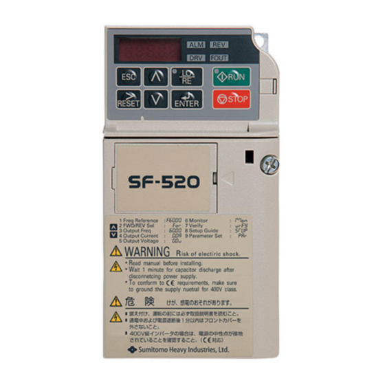
Inverter SF-520 Option
RS-232C Interface
Technical Manual
Type SI-232/JC-H
1. Make sure that this installation manual is
delivered to the end user of inverter unit.
2. Read this manual before installing or
operating the inverter unit, and store it in
a safe place for reference.
SF-520
NOTICE
Manual
No.DM2203E-1
Advertisement
Table of Contents

Related Manuals for Sumitomo Drive Technologies SI-232/JC-H


Summary of Contents for Sumitomo Drive Technologies SI-232/JC-H
- Page 1 Inverter SF-520 Option RS-232C Interface Technical Manual Type SI-232/JC-H NOTICE 1. Make sure that this installation manual is delivered to the end user of inverter unit. 2. Read this manual before installing or operating the inverter unit, and store it in a safe place for reference.
- Page 2 Copyright © 2014 Sumitomo Heavy Industries, Ltd. All rights reserved. No part of this publication may be reproduced, stored in a retrieval system, or transmitted, in any form or by any means, mechanical, electronic, photocopying, recording, or otherwise, without the prior written permission of Sumitomo. No patent liability is assumed with respect to the use of the information contained herein.
-
Page 3: Table Of Contents
Contents 1 PREFACE AND SAFETY ..4 2 RECEIVING ....8 3 PRODUCT OVERVIEW ..10 4 OPTION COMPONENTS. -
Page 4: Preface And Safety
1 Preface and Safety 1 Preface and Safety ◆ Applicable Documentation The following manuals are available for the RS-232C Interface Option: Option Unit SF-520 RS-232C Interface Option Technical Manual SF-520 Read this manual first. The Technical Manual is packaged with the RS-232C Interface Option and contains a basic overview of wiring, settings, functions, and fault diagnoses. - Page 5 1 Preface and Safety Inverter SF-520 Series Operating and Maintenance Manual To obtain instruction SF-520 No. DM2201E manuals for Sumitomo products access these sites: http:// www.shi.co.jp/PTC SF-520 Series Technical Manual No. DM2202E ◆ Terms Note: Indicates a supplement or precaution that does not cause drive damage.
- Page 6 1 Preface and Safety ◆ Registered Trademarks • Company names and product names listed in this manual are registered trademarks of those companies. ◆ Supplemental Safety Information Read and understand this manual before installing, operating, or servicing this option unit. The option unit must be installed according to this manual and local codes.
- Page 7 1 Preface and Safety CAUTION Indicates a hazardous situation, which, if not avoided, could result in minor or moderate injury. NOTICE Indicates an equipment damage message.
-
Page 8: Receiving
2 Receiving 2 Receiving ◆ Receiving Confirm the packaging after receiving the RS-232C Interface Option. If the wrong model is received or the RS-232C Interface Option does not function properly, contact your supplier. Components packaged with the option: • The RS-232C Interface for copy unit/PC communication (SI- 232/JC-H) •... - Page 9 2 Receiving ◆ Tool Requirements Use a flat-blade screwdriver with the dimensions below for installation or removal of the option cover and RS-232C option. Blade width 3.0 mm max. Blade thickness 0.6 mm max.
-
Page 10: Product Overview
3 Product Overview 3 Product Overview ◆ About this Product The RS-232C Interface Option allows the drive to be connected to a network or external device. Possible connected devices include: • LED Operator • Personal computer using PC Setup Tool These devices can be used to edit, view, and copy parameter settings in the drive. -
Page 11: Option Components
4 Option Components 4 Option Components Figure 1 SF-520 A – RJ-45 Port C – Drive Connector B – Option Model Number... - Page 12 4 Option Components ◆ Dimensions The installed Option interface adds 17.8 mm (0.70 in) to the total depth of the drive. 2.8(0.11) 15(0.60) mm(in)
-
Page 13: Installation Procedure
5 Installation Procedure 5 Installation Procedure ◆ Section Safety DANGER Electrical Shock Hazard Disconnect all power to the drive, before servicing. Failure to comply will result in death or serious injury. Wait at least one minute after all indicators are off. The drive has internal capacitors that remain charged even after the main power supply is disconnected. - Page 14 5 Installation Procedure NOTICE Damage to Equipment Use only Sumitomo connection cables or recommended cables. Failure to comply may cause the drive or option to function incorrectly. Properly connect the connectors. Failure to comply may prevent proper operation and possibly damage equipment.
- Page 15 5 Installation Procedure ◆ Attaching the Option Interface Insert a flat-blade screwdriver into the opening as shown in the diagram below to remove the option cover from the drive. Insert the connector on the back of the interface into the CN5 port and click into position.
- Page 16 5 Installation Procedure ◆ Removing the option interface Use a flat-blade screwdriver as shown in the diagram to press gently against the small openings and disconnect the option unit. underside of interface unit flat-blade screwdriver...
- Page 17 5 Installation Procedure ◆ Connecting Peripheral Devices to the RS-232C Interface Option NOTICE: Only use specific cables recommended by Sumitomo. Sumitomo cannot guarantee proper operation if non-specified cables are used. SF-520 connect SI-232/JC-H SI-232/JC-H <2> <1> LED Operator PC Setup Tool...
- Page 18 5 Installation Procedure <1> Use the LED operator cable, ICS-1 or ICS-3. <2> Only use the cable, PN: WV103, when connecting the drive to a PC.
-
Page 19: Related Drive Parameters
6 Related Drive Parameters 6 Related Drive Parameters Name Description Default Determines if the drive will stop when the digital operator is removed in Local mode or Operation with b1-02 set to zero. Selection 00: Disabled - The drive will o2-06 when Digital not stop when the digital... -
Page 20: Troubleshooting
7 Troubleshooting 7 Troubleshooting Problems with the option interface may trigger an operator error. Refer to the SF-520 Technical Manual for all other errors. ◆ Fault LED Operator Fault Name Display Digital operator connection fault Cause Possible solution • Check the connection between the LED LED operator is operator and the drive not properly... -
Page 21: Specifications
8 Specifications 8 Specifications ◆ Drive Specification Item Specification Model SI-232/JC-H: RS-232C Interface for use with Number copy unit and PC communication Storage/ Installation Indoors (an area free from oil mist and dust) Area Ambient -10 to +50°C Temperature Humidity... -
Page 22: Warranty
9 Warranty 9 Warranty ◆ Warranty policy on inverter The warranty period is 18 months from date of Warranty shipment or 12 months after initial opera-tion, period whichever comes first. In the event that any problem or damage to the Product arises during the "Warranty Pe-riod"... - Page 23 9 Warranty Not withstanding the above warranty, the warranty as set forth herein shall not apply to any problem or damage to the Product that is caused by: 1. Installation, connection, combination or integration of the Product in or to the other equipment or machine that rendered by any person or entity other than the Seller.
- Page 24 9 Warranty 7. Earthquake, fire, flood, salt air, gas, lightning, acts of God or any other reasons be-yond the control of the Seller; Warranty 8. Normal wear and tear, or deterioration of the exclusion Product's parts, such as the cooling fan bearings; 9.
- Page 25 Speci cations, dimensions, and other items are subject to change without prior notice. No.DM2203E-1.2 EE01 Printed 2015.03...
Need help?
Do you have a question about the SI-232/JC-H and is the answer not in the manual?
Questions and answers