Table of Contents
Advertisement
Quick Links
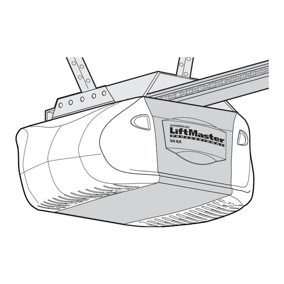
GARAGE DOOR OPENER
Model 2595LM 3/4 HP
For Residential Use
Install on Sectional Doors ONLY
THIS OPERATOR IS INTENDED FOR USE ONLY WITH I-BEAM RAILS.
Owner's Manual
Please read this manual and the enclosed safety materials carefully!
■
Fasten the manual near the garage door after installation.
■
The door WILL NOT CLOSE unless the Protector System
■
properly aligned.
Periodic checks of the opener are required to ensure safe operation.
■
The model number label is located under the light lens on the left side
■
panel of your opener.
®
The Chamberlain Group, Inc.
845 Larch Avenue
Elmhurst, Illinois 60126-1196
www.liftmaster.com
is connected and
®
®
Advertisement
Table of Contents

Related Manuals for Chamberlain 2595LM 3/4 HP


Summary of Contents for Chamberlain 2595LM 3/4 HP
- Page 1 GARAGE DOOR OPENER Model 2595LM 3/4 HP For Residential Use Install on Sectional Doors ONLY THIS OPERATOR IS INTENDED FOR USE ONLY WITH I-BEAM RAILS. Owner’s Manual Please read this manual and the enclosed safety materials carefully! ■ Fasten the manual near the garage door after installation.
-
Page 2: Table Of Contents
Safety Symbol and Signal Word Review This garage door opener has been designed and tested to offer safe service provided it is installed, operated, maintained and tested in strict accordance with the instructions and warnings contained in this manual. WARNING... -
Page 3: Preparing Your Garage Door
To prevent damage to garage door and opener: • ALWAYS disable locks BEFORE installing and operating the opener. • ONLY operate garage door opener at 120V, 60 Hz to avoid malfunction and damage. Tools needed During assembly, installation and adjustment of the opener, instructions will call for hand tools as illustrated below. -
Page 4: Planning
Planning Identify the type and height of your garage door. Survey your garage area to see if any of the conditions below apply to your installation. Additional materials may be required. You may find it helpful to refer back to this page and the accompanying illustrations as you proceed with the installation of your opener. -
Page 5: Carton Inventory
Carton Inventory Your garage door opener is packaged in two cartons which contain the motor unit and all parts illustrated below. Accessories will depend on the model Security 3-Button Remote Control Motion Detecting Door Control Panel Motor Unit With Light Lenses... -
Page 6: Assembly
ASSEMBLY STEP 1 Attach the Rail to the Motor Unit To avoid installation difficulties, do not run the garage door opener until instructed to do so. • Remove the bolt and lock nut from the top of the motor unit. -
Page 7: Tighten The Chain
4. Disable all locks and remove all ropes connected to garage door BEFORE installing opener to avoid entanglement. 5. Install garage door opener 7 feet (2.13 m) or more above floor. 6. Mount emergency release handle 6 feet (1.83 m) above floor. -
Page 8: Installation Step
INSTALLATION STEP 1 Determine the Header Bracket Location WARNING To prevent possible SERIOUS INJURY or DEATH: • Header bracket MUST be RIGIDLY fastened to CAUTION structural support on header wall or ceiling, otherwise garage door might not reverse when required. DO NOT install header bracket over drywall. -
Page 9: Install The Header Bracket
INSTALLATION STEP 2 Install the Header Bracket You can attach the header bracket either to the wall above the garage door, or to the ceiling. Follow the instructions which will work best for your particular requirements. Do not install the header bracket over drywall. -
Page 10: Attach The Rail To The Header Bracket
INSTALLATION STEP 3 Attach the Rail to the Header Bracket • Position the opener on the garage floor below the header bracket. Use packing material as a protective base. NOTE: If the door spring is in the way you’ll need help. Have someone hold the opener securely on a temporary support to allow the rail to clear the spring. -
Page 11: Hang The Opener
Lag Screw 5/16"-18x1-7/8" Hex Bolt 5/16"-18x7/8" Nut 5/16"-18 To avoid possible SERIOUS INJURY from a falling garage door opener, fasten it SECURELY to structural supports of the garage. Concrete anchors MUST be used if installing any brackets into masonry. Figure 1 Measure Distance Lock Washer 5/16"... -
Page 12: Install The Door Control
CAUTION INSTALLATION STEP 6 Install the Door Control Locate door control within sight of the door at a minimum height of 5 feet (1.5 m) where small children cannot reach, and away from moving parts of the door and door hardware. The installation surface must be smooth and flat. -
Page 13: Install The Lights
• Reverse the procedure to close the lens. • If the bulbs burn out prematurely due to vibration, replace with a Garage Door Opener bulb. NOTE: Use only standard light bulbs. The use of short neck or speciality light bulbs may overheat the endpanel or light socket. -
Page 14: Electrical Requirements
WARNING INSTALLATION STEP 9 Electrical Requirements CAUTION To avoid installation difficulties, do not run the opener at this time. To reduce the risk of electric shock, your garage door opener has a grounding type plug with a third grounding pin. This plug will only fit into a grounding type outlet. -
Page 15: Install The Protector System
INSTALLATION STEP 10 Install The Protector System The safety reversing sensor must be connected and aligned correctly before the garage door opener will move in the down direction. IMPORTANT INFORMATION ABOUT THE SAFETY REVERSING SENSOR When properly connected and aligned, the sensor will detect an obstacle in the path of its electronic beam. -
Page 16: Installing The Brackets
INSTALLING THE BRACKETS Be sure power to the opener is disconnected. Install and align the brackets so the sensors will face each other across the garage door, with the beam no higher than 6" (15 cm) above the floor. They may be installed in one of three ways, as follows: Garage door track installation (preferred): •... -
Page 17: Aligning The Safety Sensors
MOUNTING AND WIRING THE SAFETY SENSORS • Slide a 1/4"-20x1/2" carriage bolt head into the slot on each sensor. Use wing nuts to fasten sensors to brackets, with lenses pointing toward each other across the door. Be sure the lens is not obstructed by a bracket extension (Figure 4). -
Page 18: Fasten The Door Bracket
INSTALLATION STEP 11 Fasten the Door Bracket Follow instructions which apply to your door type as illustrated below or on the following page. A horizontal reinforcement brace should be long enough to be secured to two or three vertical supports. A vertical reinforcement brace should cover the height of the top panel. -
Page 19: Sectional Doors Only
INSTALLATION STEP 12 Connect Door Arm to Trolley SECTIONAL DOORS ONLY • Make sure garage door is fully closed. Pull the emergency release handle to disconnect the outer trolley from the inner trolley. Slide the outer trolley back (away from the door) about 2" (5 cm) as shown in Figures 1, 2 and 3. -
Page 20: Adjustment
ADJUSTMENT STEP 1 Adjust the UP and DOWN Travel Limits Limit adjustment settings regulate the points at which the door will stop when moving up or down. To operate the opener, press the Door Control push bar. Run the opener through a complete travel cycle. •... -
Page 21: Adjustment
ADJUSTMENT STEP 2 Adjust the Force Force adjustment controls are located on the right side panel of the motor unit. Force adjustment settings regulate the amount of power required to open and close the door. If the forces are set too light, door travel may be interrupted by nuisance reversals in the down direction and stops in the up direction. -
Page 22: Test The Safety Reversal System
The door will not move more than an inch (2.5 cm), and the opener lights will flash. The garage door opener will not close from a remote if the indicator light in either sensor is off (alerting you to the fact that the sensor is misaligned or obstructed). -
Page 23: Operation
• The wall-mounted Door Control: Hold the push button or bar down until the door starts to move. • The Keyless Entry (See Accessories): If provided with your garage door opener, it must be programmed before use. See Programming. When the opener is activated (with the safety reversing sensor correctly installed and aligned): 1. -
Page 24: Using The Wall-Mounted Door Control
Using the Wall-Mounted Door Control THE MOTION DETECTING DOOR CONTROL Press the push bar to open or close the door. Press again to reverse the door during the closing cycle or to stop the door while it's opening. This door control contains a motion detector that will automatically turn on the light when it detects a person entering... -
Page 25: Care Of Your Garage Door Opener
CARE OF YOUR OPENER LIMIT AND FORCE ADJUSTMENTS: Weather conditions may cause some minor changes in door operation requiring some re- adjustments, particularly during the first year of operation. Pages 20 and 21 refer to the limit and force adjustments. Only a screwdriver is required. -
Page 26: Having A Problem
Installation Step 10. 12. The opener lights don't turn on: • Replace the light bulbs (100 watts maximum). Use a standard neck garage door opener bulb if regular bulb burns out. 13. The opener lights don't turn off: • Is the Light feature on? Turn it off. -
Page 27: Programming
The owner of the copyright in the garage door opener does not authorize the purchaser or supplier of the non-rolling code transmitter to circumvent that technical measure. -
Page 28: To Add, Reprogram Or Change A Keyless Entry Pin
To Add, Reprogram or Change a Keyless Entry PIN NOTE: Your new Keyless Entry must be programmed to operate your garage door opener. USING THE “LEARN” BUTTON 1. Press and release the “learn” button on motor unit. The learn indicator light will glow steadily for 30 seconds. -
Page 29: Repair Parts
REPAIR PARTS Rail Assembly Parts Installation Parts KEY PART 41A5276-24 973LM 10A20 29B137 41A2828 41B4494-1 41A5047 41A4353 41A5034 178B34 178B35 41A5266-1 41A5281 41A2770-8 114A2677 114A2677SP Owner’s manual - Spanish PART DESCRIPTION 4A1008 Master link kit 41A2780 Chain pulley bracket 41A3489 Complete trolley assembly 3707CH 7' (2.1 m) Rail assembly... -
Page 30: Motor Unit Assembly Parts
Motor Unit Assembly Parts PART DESCRIPTION 41C5069 Chassis support bracket assy. kit 41A4208-2 Chain spreader 41A5658 Gear and sprocket assembly Complete with: Spring washer, thrust washer, retaining ring, bearing plate, roll pins (2), drive gear and worm gear, helical gear w/retainer and grease 41A2817 Drive/worm gear kit w/grease,... -
Page 31: Accessories
995LM Remote Light Control: Enables homeowner to turn on a lamp, television or other appliance from their car with their garage door opener remote or from anywhere in their home with an additional Liftmaster Security✚ 971LM Single-Button Security✚ Control: Includes visor clip. -
Page 32: Liftmaster Service Is On Call
LIFETIME MOTOR LIMITED WARRANTY The Chamberlain Group, Inc. (“Seller”) warrants to the first retail purchaser of this product, for the residence in which this product is originally installed, that it is free from defect in materials and/or workmanship for a period of five years from the date of purchase and that the motor is free from defect in materials and/or workmanship for the lifetime of the product.
Need help?
Do you have a question about the 2595LM 3/4 HP and is the answer not in the manual?
Questions and answers