Broan CLSC2 Series Installation Use And Care Manual
Hide thumbs
Also See for CLSC2 Series:
- Installation use and care manual (72 pages) ,
- Installation use and care manual (72 pages)

Related Manuals for Broan CLSC2 Series


Summary of Contents for Broan CLSC2 Series
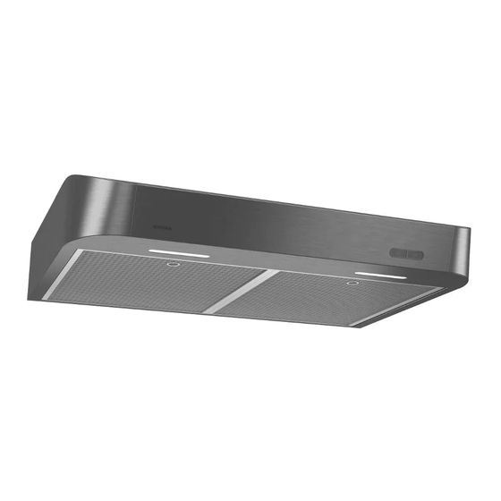
- Page 1 WWW.BROAN.COM WWW.BROAN.CA RANGE HOOD Series: CLDA1 and CLSC2 INSTALLATION, USE AND CARE MANUAL Serial number: 99045653-003F...
-
Page 2: Table Of Contents
Connect the Wiring ..... . 19 LED Light Bulbs (CLSC2 Series only) ..20 Install the Filters . -
Page 3: Safety
READ AND SAVE THESE INSTRUCTIONS Intended for domestic cooking only INSTALLER: LEAVE THIS MANUAL WITH HOMEOWNER. In U.S.A., register your range hood online at www.broan.com In Canada, register your range hood online at www.broan.ca WARNING TO REDUCE THE RISK OF FIRE, ELECTRIC SHOCK, OR INJURY TO PERSONS, OBSERVE THE FOLLOWING: •... - Page 4 WARNING TO REDUCE THE RISK OF A RANGE TOP GREASE FIRE: a) Never leave surface units unattended at high settings. Boilovers cause smoking and greasy spillovers that may ignite. Heat oils slowly on low or medium settings. b) Always turn hood ON when cooking at high heat or when flambeing food (i.e.: Crêpes Suzette, Cherries Jubilee, Peppercorn Beef Flambé).
-
Page 5: Operation
Let the blower run for a few minutes to clear the air after you turn off the range. This will help keep the whole kitchen cleaner and fresher. Operate the hood as follows: CLSC2 SERIES BLOWER SWITCH LIGHT SWITCH Turns blower on to LOW speed. -
Page 6: Cleaning And Maintenance
Cleaning and Maintenance Proper maintenance of the Range Hood will assure proper performance of the unit. MOTOR The motor is permanently lubricated and never needs oiling. If the motor bearings make excessive or unusual noise, replace the motor with the exact service motor. The fan blade should also be replaced. -
Page 7: Installation
Drill, 1/8” drill bit and 1½” hole saw (to mark holes for ducting and cut electrical access hole) • 7/64” drill bit (to drill holes for EZ1 brackets mounting screws, not for CLSC2 Series) • Wood shims (2) and wood screws (4) (required for standard installation to framed cabinet) •... -
Page 8: Contents
(6) N 5/8” (6) N 1/2” RD. HD. OUNTERSUNK CREWS CREWS *** F IND PARTS BAG BEHIND THE DAMPER ASSEMBLY INSIDE OF HOOD CLSC2 Series (1) P ARTS ONTAINING (6) N 5/8” (2) LED B (4 W, GU10) ULBS RD. HD. -
Page 9: Prepare The Hood
Prepare the Hood 1 ] If present, remove all protective polyfilm from the hood and/or parts. 2 ] Using the finger cup (CLDA1 Series) or the tab (CLSC2 Series), remove the grease filters from the hood by pushing down... - Page 10 5 ] Remove 7” Round Duct Plate from top/back of hood (see illustration below). 7” ROUND DUCT PLATE 2 SCREWS 6 ] Remove Electrical Power Cable Knockout from top (vertical exhaust) or back (horizontal exhaust) of hood. Install an appropriate strain relief, 1/2” diameter (not included). ELECTRICAL POWER CABLE KNOCKOUT...
- Page 11 DUCTED INSTALLATION ONLY 8 ] Remove 3¼” x 10” vertical, 3¼” x 10” horizontal, or 7-inch round knockout plate as appropriate for your ducting method (see F 1 A and 1 B). IGURES IGURE IGURE 7” ROUND KNOCKOUT PLATE ( ALSO REMOVE VERTICAL KNOCKOUT PLATE 3¼”...
-
Page 12: Prepare The Hood Location
This manual covers 2 kinds of installation: the standard (without EZ1 brackets) and the EZ1 one-person installation system (using included template and brackets). Please note that the EZ1 one-person installation system is not available for the CLSC2 Series. For the standard installation, go to page 17. - Page 13 4 ] Drill a 1/8” dia. pilot hole for house wiring, at A location on template. 5 ] Use a sharp pencil or 1/8” drill bit to mark the locations for the appropriate duct access holes (16 locations for 7” round duct, or 4 corner locations for rectangular duct). Remove the template.
- Page 14 FRAMELESS CABINET Refer to the marking on brackets to determine the correct installation side and orientation. 7/64” Align the corresponding bracket to the cabinet side, while placing rear end of bracket against the wall. Draw a line on the outer edge of the bracket (as shown). ...
-
Page 15: Install The Hood (Ez1 Bracket)
Install the Hood (EZ1 Bracket) OTE: The following procedure applies to both framed or frameless cabinet installations. 1 ] Run house power cable between service panel and hood location. 2 ] There are 2 pairs of recessed holes on each side of the top of the hood (on rear: A and B, on front C and D on illustration below);... - Page 16 7 ] For framed cabinet, secure the hood to the EZ1 brackets using 4 no. 8-18 x 1/2” metal screws (included in parts bag). Insert 2 screws per side, in the slots (as shown in insets on illustration below). 8 ] For frameless cabinet, secure the hood to the cabinet using 4 no. 8 x 5/8” round head wood screws (included in parts bag).
-
Page 17: Standard Installation
Standard Installation (without EZ1 brackets) 1 ] Use the proper diagram below for placement of ductwork and electrical cutout in cabinet or wall. For a non-ducted installation, DO NOT cut a duct access hole, only cut the hole for electrical wiring. 3¼"... -
Page 18: Install The Hood (Standard Installation)
Install the Hood (Standard Installation) 1 ] Run house power cable between service panel and hood location. Run the house power cable into the hood through the strain relief previously installed in step 6 on page 10. 2 ] Hang hood from (4) mounting screws previously installed. Slide hood back towards wall until mounting screw heads are engaged in narrow end of keyhole slots in top of hood. -
Page 19: Connect The Wiring
Connect the Wiring WARNING Risk of electric shock. Electrical wiring must be done by qualifi ed personnel in accordance with all applicable codes and standards. Before connecting wires, switch power off at service panel and lock service disconnecting means to prevent power from being switched on accidentally. -
Page 20: Led Light Bulbs (Clsc2 Series Only)
LED Light Bulbs (CLSC2 Series only) The CLSC2 Series range hoods require two LED light bulbs (120 V, 4 W max., with GU10 base), included. BULB LEADS BULB LEAD SUCTION GROOVES CUP TOOL (IN SOCKET) 1 ] Align the bulb leads with the small indentations located on the border of the lamp location on hood (see inset above), then install the bulbs by placing the bulb leads into their grooves in the socket. -
Page 21: Wiring Diagrams
User interface mounted to J10 on back of control board. FAN MOTOR Control Board R (Low) O (Medium) BK (High) Line Neutral BN/W Ground CLSC2 SERIES COLOR CODE BLACK GREEN/YELLOW ref: 990729751_REV-A BLUE ORANGE BROWN BN/W BROWN/WHITE WHITE Lights Motor... -
Page 22: Service Parts
ARTS AND EPAIRS In order to ensure your unit remains in good working condition, you must use Broan-NuTone LLC or Venmar Ventilation ULC genuine replacement parts only. Broan-NuTone LLC or Venmar Ventilation ULC genuine replacement parts are specially designed for each unit and are manufactured to comply with all the applicable certification standards and maintain a high standard of safety. - Page 23 EPAIRS In order to ensure your unit remains in good working condition, you must use Broan-NuTone LLC genuine replacement parts only. Broan- NuTone LLC genuine replacement parts are specially designed for each unit and are manufactured to comply with all the applicable certification standards and maintain a high standard of safety.
-
Page 24: Warranty
Limited Warranty Warranty Period and Exclusions: Broan-NuTone LLC and Venmar Ventilation ULC (either being the “Company”) warrants to the original consumer purchaser of its product (“you”) that the product (the “Product”) will be free from material defects in the Product orits workmanship for a period of one (1) year from the date of original purchase (or such longer period as may be required by applicable law).
Need help?
Do you have a question about the CLSC2 Series and is the answer not in the manual?
Questions and answers