Sign In
Upload
Download
Table of Contents
Contents
Add to my manuals
Delete from my manuals
Share
URL of this page:
HTML Link:
Bookmark this page
Add
Manual will be automatically added to "My Manuals"
Print this page
×
Bookmark added
×
Added to my manuals
Manuals
Brands
Broan Manuals
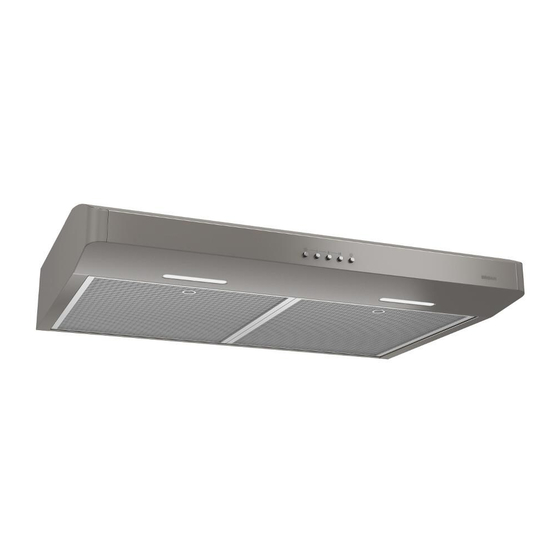
Ventilation Hood
CRDE1 Series
Installation use and care manual
Broan CRDE1 Series Installation Use And Care Manual
Hide thumbs
1
Table Of Contents
2
3
4
5
6
7
8
9
10
11
12
13
14
15
16
17
18
19
20
21
22
23
24
page
of
24
Go
/
24
Contents
Table of Contents
Bookmarks
Table of Contents
Table of Contents
Safety
Operation
Cleaning and Maintenance
Motor
Grease Filter
Non-Ducted Recirculation Filter
Fan Blade
Stainless Steel Cleaning
Painted Finish Cleaning
Installation
Recommended Tools and Accessories for Installation
Install Ductwork (Ducted Installations Only)
Contents
Prepare the Hood
Prepare the Hood Location
EZ1 Person Installation
Install the Hood (EZ1 Bracket)
Standard Installation
Install the Hood (Standard Installation)
Connect the Wiring
Install the Filters
Wiring Diagram
Service Parts
Warranty
Advertisement
Quick Links
Download this manual
WWW.BROAN.COM
RANGE HOOD
Series: CRDE1 and CRSF1
INSTALLATION, USE
AND CARE MANUAL
Serial number:
99045663-002E
Table of
Contents
Previous
Page
Next
Page
1
2
3
4
5
Advertisement
Table of Contents
Need help?
Do you have a question about the CRDE1 Series and is the answer not in the manual?
Ask a question
Questions and answers
Related Manuals for Broan CRDE1 Series
Ventilation Hood Broan CBD1 Series Instructions Manual
(24 pages)
Ventilation Hood Broan CBX1 series Instruciton Manual
(17 pages)
Ventilation Hood Broan CBD3 Series Instructions For Use Manual
Range hoods (17 pages)
Ventilation Hood Broan CJD1 SERIES Installation And Setup Manual
Range hood (16 pages)
Ventilation Hood Broan CJD3 Series Instruction Manual
Broan range hood (17 pages)
Ventilation Hood Broan CRDN1 SERIES Installation Use And Care Manual
(48 pages)
Ventilation Hood Broan 88000 SERIES Installation Instructions Manual
88000 series/microtek system iv convertible range hood (9 pages)
Ventilation Hood Broan CLDH1 Series Installation Use And Care Manual
(22 pages)
Ventilation Hood Broan BCSQ1 Series Installation Use And Care Manual
(18 pages)
Ventilation Hood Broan CLDA1 Series Installation Use And Care Manual
(72 pages)
Ventilation Hood Broan CLSC1 Installation Use And Care Manual
(24 pages)
Ventilation Hood Broan CLSC2 Series Installation Use And Care Manual
(24 pages)
Ventilation Hood Broan Antero CLSC230WW Installation Use And Care Manual
(72 pages)
Ventilation Hood Broan CLDA136SS Installation Use And Care Manual
(24 pages)
Ventilation Hood Broan CRSF1 Series Installation Use And Care Manual
(24 pages)
Ventilation Hood Broan CLDA130BLS Installation Use And Care Manual
(24 pages)
This manual is also suitable for:
Crsf1 series
Table of Contents
Print
Rename the bookmark
Delete bookmark?
Delete from my manuals?
Login
Sign In
OR
Sign in with Facebook
Sign in with Google
Upload manual
Upload from disk
Upload from URL


Need help?
Do you have a question about the CRDE1 Series and is the answer not in the manual?
Questions and answers