Table of Contents
Advertisement
Quick Links
Advertisement
Table of Contents

Related Manuals for Zenitel Vingtor Stentofon FCDC1


Summary of Contents for Zenitel Vingtor Stentofon FCDC1
- Page 1 Configuration Manual Flowire Converter FCDC1 / FCDC2 TECHNICAL MANUAL A100K11422...
- Page 2 About this Document Document Scope This document provides a detailed guide to the system setup and configuration of the FCDC1 and FCDC2 Flowire Converter in creating IP networks using conventional telecom star-wired infrastructure (2-wire). Relevant Products Product Description Item Name Item No.
-
Page 3: Table Of Contents
Contents 1 Product Description ......................4 1.1 General Description .......................4 1.2 Areas of Application .......................5 1.2.1 Retrofitting Older Intercom & Telephone Systems ............5 1.2.2 Remote IP Intercom Locations In New Buildings ............5 2 Upgrading Conventional Star-Wired Infrastructure ............6 2.1 The Conventional System .....................6 2.2 Power on Conventional Infrastructure ................7 2.3 Precaution &... -
Page 4: Product Description
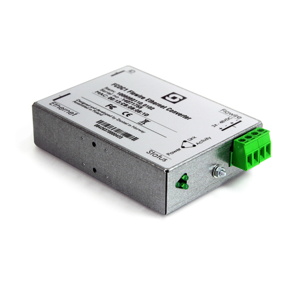
Product Description 1.1 General Description The Flowire Converter enables Ethernet to run on the same two wires as power, providing simpler cabling and opening up for longer cable hauls. The Flowire converter is also capable of powering the Ethernet devices (Vingtor-Stentofon IP intercom stations) attached to it via spare pairs. Status Indicators Ground Connection Flowire/Power Ports... -
Page 5: Areas Of Application
1.2 Areas of Application The main areas of application for the Flowire Converter are: ● Retrofitting older communication systems ● Providing Ethernet connectivity to remote locations in buildings 1.2.1 Retrofitting Older Intercom & Telephone Systems ● Analog and digital intercom systems ● Analog and digital telephone systems The above solutions typically use a conventional star-wired telecom infrastructure with 0.5 mm AWG) single-pair twisted cables. -
Page 6: Upgrading Conventional Star-Wired Infrastructure
Upgrading Conventional Star-Wired Infrastructure 2.1 The Conventional System A conventional star-wired infrastructure supports analog and digital intercom and telephone systems. These star-wired telecom infrastructures are typically used in both marine and onshore intercom applications. Figure 3 Conventional star-wired infrastructure In this solution, you will have a centralized equipment rack with the following equipment: ●... -
Page 7: Power On Conventional Infrastructure
Conventional star-wired telecom infrastructures commonly use one twisted wire pair to each telecom device. However, many systems, like AlphaCom, use two twisted pairs for each telecom device 2.2 Power on Conventional Infrastructure In an analog and digital telecom/intercom system, it is usually a requirement to power the telephones/ intercoms from the central equipment rack, thus supplying the power over the subscriber line. -
Page 8: System Configuration With Central Powering Of Remote Intercoms
2.5 System Configuration with Central Powering of Remote Intercoms FCDC1 FCDC1 2-wire 2-wire FCDC1 > 0 5 m 2-wire Junction 2-wire/multipair cable FCDC2 2-wire FCDC1 2-wire Gather multipairs when connecting to Flowire FCDC1 FCDC2 2-wire/multipair cable > 0 5 m Junction 2-wire FCDC1 2-wire Main distribution frame 2-wire FCDC1 2-wire... -
Page 9: System Configuration With Local Powering Of Remote Intercoms
2.6 System Configuration with Local Powering of Remote Intercoms 2 wire 2 wire Multipair cable Junction Flat cable 2 wire Cross connect 2 wire Flat cable Junction Multipair cable 2 wire Main distribution frame 2 wire 2 wire 2wire 2 wire Figure 6 Conventional analog/digital system configuration FCDC2 PoE injector 2-wire long haul... -
Page 10: System Configuration With Industrial & Ex Devices
2.7 System Configuration with Industrial & Ex Devices The Ex device (TFIX station, EAPFX access panel) located in a hazardous zone is connected to the central equipment rack located in the safe zone using an Ex certified 2-wire shielded cable. FCDC2 is used to extend the Ethernet connection and support power distribution on the 2-wire cabling infrastructure. -
Page 11: Connections & Indications
Connections & Indications 3.1 Flowire Connection The Flowire Converter must be connected to the Flowire star configuration using twisted cabling as shown. The red wire is the positive supply voltage while the black wire is the negative supply voltage. The power supply voltage used depends on the type of devices in the star configuration. -
Page 12: Mounting & Recommendations
Mounting & Recommendations 4.1 Mounting the Flowire Converter The Flowire Converter should be mounted on-wall by using 2 x 4 mm screws or on NS35 DIN rail by using the mounting clips provided in a normal and ventilated indoor environment with a temperature of maximum 55ºC. -
Page 13: Power Requirements
4.2 Power Requirements A Flowire Converter needs at least 18V to operate, nominal voltage is 24V to 48V, and maximum voltage is 56V. The voltage at the remote Flowire Converter should never drop below half of the PSU’s output voltage. To power a Vingtor-Stentofon IP Intercom Station through its Ethernet port, we recommend at least 40V at the remote site. -
Page 14: Troubleshooting
Troubleshooting 5.1 Power for Stable Connection at Remote Site The minimum voltage at the remote end for PoE is 40VDC. The minimum voltage for the TFIX Ex intercoms and EAPFX Ex access panels is 18VDC. If you are not getting sufficient voltage for a stable connection at the remote site, you can: ●... - Page 15 A100K11422 Flowire Converter Configuration Manual...
-
Page 16: A: Power Consumption & Distances For Typical Cables
A: Power Consumption & Distances for Typical Cables The table below shows theoretical point-to-point distances for different cable types at different levels of power consumption at the remote location. All distances are calculated for 48V output from the PSU. Cable Type Resistance Intercom Intercom... -
Page 17: B: Advanced Configuration
B: Advanced Configuration IP addresses on a Flowire device can be set either by setting a static IP address or having one assigned from a temporary DHCP server. The Flowire device has, by default, DHCP enabled on one of their networking interfaces. The DHCP can be disabled as described in section “B.2 Disabling DHCP”. -
Page 18: Disabling Dhcp
B.2 Disabling DHCP This feature is supported in Flowire software versions 4.1.3.3 and later. In case there is an explicit need to turn off the DHCP client on the device, this can be done via the device web interface. To disable DHCP: ●... -
Page 19: Network Management Key (Nmk) Configuration
B.3 Network Management Key (NMK) Configuration To set a new NMK password: 1. Log into the Flowire device by entering its IP address (e.g. 10.5.202.80) in a web browser. 2. Click the Upgrade form button 3. Enter a new password in the Flowire NMK field 4. Click Change NMK The NMK Password must be between 8 and 64 characters long, and is case sensitive. -
Page 20: Igmp Settings
It is good practice to label the Flowire device with the new NMK. Default NMK: HomePlugAV0123 2.1 IGMP Settings It is possible to configure IGMP settings in the Flowire web interface. Figure 11 IGMP Settings 2.1.1 IGMP Querier In order to secure the reliability of multicast handling, the network should have an active IGMP querier. -
Page 21: Cco Settings
2.2 CCo Settings Figure 12 Configured PLC Role - CCo, Not CCo, Auto In the Flowire web interface, each Flowire unit has a setting for CCo (Central Coordinator). In every Flowire network, there is always one CCo, but this is, by default, automatically selected. If the CCo should fail, another Flowire unit on the network is automatically selected to be CCo. -
Page 22: C: Software Upgrade
C: Software Upgrade Depending on how old the current software on the Flowire device is, upgrade procedures are carried out differently. If the current software version is 4.x, upgrades can be done in one of two ways: ● Intercom Management Tool (VS-IMT) on the PC (see “C.1 Upgrading via VS-IMT on PC”) ●... - Page 23 After the Flowire devices have been discovered: ● Select all Flowire devices ● Click NEXT twice, skipping STEP 2 Identify stations ● Make sure the correct Flowire software is selected. ● CTRL+Click to select multiple devices for upgrade A100K11422 Flowire Converter Configuration Manual...
- Page 24 ● Click the Upgrade button to start the process. The upgrade process should take about 1 minute per Flowire device. When the upgrade progress bar is at 100%: ● Click NEXT twice ● Click FINISH to complete the upgrade procedure A100K11422 Flowire Converter Configuration Manual...
-
Page 25: Upgrade Via Web Interface On Flowire Device
C.2 Upgrade via Web Interface on Flowire Device L For software version 4.x C.2.1 TFTP Server Setup ● Start the Tftpd program on the PC In the TFTP server: ● Browse to the directory where the Flowire software is stored ●... - Page 26 ● Enter the TFTP Server IP address and select either: - Upgrade – Upgrades the firmware and does nothing else - Full upgrade – Upgrades the firmware and resets to factory setting L For Full upgrade, resetting the device to factory default setting also implies changing the NMK password to its factory default.
- Page 27 Zenitel and its subsidiaries assume no responsibility for any errors that may appear in this publication, or for damages arising from the information therein. VINGTOR-STENTOFON products are developed and marketed by Zenitel. The company’s Quality Assurance System is certified to meet the requirements in NS-EN ISO 9001. Zenitel reserves the right to modify designs and alter specifications without notice.
Need help?
Do you have a question about the Vingtor Stentofon FCDC1 and is the answer not in the manual?
Questions and answers