Table of Contents
Advertisement
Quick Links
Advertisement
Table of Contents

Related Manuals for Zenitel Vingtor Stentofon FCDC3


Summary of Contents for Zenitel Vingtor Stentofon FCDC3
- Page 1 Configuration Manual Flowire Converter FCDC3 TECHNICAL MANUAL A100K11958...
- Page 2 About this Document Document Scope This document provides a detailed guide to the system setup and configuration of the FCDC3 Flowire Converter in creating IP networks using conventional telecom star-wired infrastructure (2-wire). Relevant Products Product Description Item Name Item No. Flowire Converter, 24-48V DC FCDC3 1008080310...
-
Page 3: Table Of Contents
Contents 1 Product Description ......................4 1.1 General Description .......................4 1.2 Areas of Application .......................5 1.2.1 Retrofitting Older Intercom & Telephone Systems ............5 1.2.2 Remote IP Intercom Locations in New Buildings ............5 2 Upgrading Conventional Star-Wired Infrastructure ............6 2.1 The Conventional System .....................6 2.2 Power on Conventional Infrastructure ................7 2.3 Precaution &... -
Page 4: Product Description
Product Description 1.1 General Description The Flowire Converter enables Ethernet to run on the same two wires as power, providing simpler cabling and opening up for longer cable hauls. The Flowire converter is also capable of powering the Ethernet devices (Vingtor-Stentofon IP intercom stations) attached to it via spare pairs. Password Reset Button PoE On/Off Switch Ethernet Port... -
Page 5: Areas Of Application
1.2 Areas of Application The main areas of application for the Flowire Converter are: ● Retrofitting older communication systems ● Providing Ethernet connectivity to remote locations in buildings 1.2.1 Retrofitting Older Intercom & Telephone Systems ● Analog and digital intercom systems ● Analog and digital telephone systems The above solutions typically use a conventional star-wired telecom infrastructure with 0.5 mm AWG) single-pair twisted cables. -
Page 6: Upgrading Conventional Star-Wired Infrastructure
Upgrading Conventional Star-Wired Infrastructure 2.1 The Conventional System A conventional star-wired infrastructure supports analog and digital intercom and telephone systems. These star-wired telecom infrastructures are typically used in both marine and onshore intercom applications. Figure 3 Conventional star-wired infrastructure In this solution, you will have a centralized equipment rack with the following equipment: ●... -
Page 7: Power On Conventional Infrastructure
Conventional star-wired telecom infrastructures commonly use one twisted wire pair to each telecom device. However, many systems, like AlphaCom, use two twisted pairs for each telecom device 2.2 Power on Conventional Infrastructure In an analog and digital telecom/intercom system, it is usually a requirement to power the telephones/ intercoms from the central equipment rack, thus supplying the power over the subscriber line. -
Page 8: System Configuration With Central Powering Of Remote Intercoms
2.5 System Configuration with Central Powering of Remote Intercoms PoE enabled FCDC3 Audio Server PoE enabled FCDC3 2-wire PoE enabled 2-wire FCDC3 2-wire PoE enabled Junction 2-wire/multipair cable FCDC3 2-wire FCDC3 PoE disabled 2-wire Gather multipairs when PoE enabled connecting to Flowire PoE disabled FCDC3 FCDC3 2-wire/multipair cable Junction FCDC3 2-wire... -
Page 9: System Configuration With Local Powering Of Remote Intercoms
2.6 System Configuration with Local Powering of Remote Intercoms 2 wire 2 wire Multipair cable Junction Flat cable 2 wire Cross connect 2 wire Flat cable Junction Multipair cable 2 wire Main distribution frame 2 wire 2 wire 2wire 2 wire Figure 6 Conventional analog/digital system configuration FCDC3 PoE injector Audio Server... -
Page 10: System Configuration With Industrial & Ex Devices
2.7 System Configuration with Industrial & Ex Devices The Ex device (TFIX station, EAPFX access panel) located in a hazardous zone is connected to the central equipment rack located in the safe zone using an Ex certified 2-wire shielded cable. FCDC3 is used to extend the Ethernet connection and support power distribution on the 2-wire cabling infrastructure. -
Page 11: Connections & Indications
Connections & Indications Password Reset Button 3.1 Flowire Connection PoE On/Off Switch The Flowire Converter (FCDC3) must be connected Ethernet Port to the Flowire network star configuration using twisted cabling with positive and negative DC voltage connected as shown on the label. The power supply voltage used depends on the type of devices in the star configuration. -
Page 12: Mounting & Recommendations
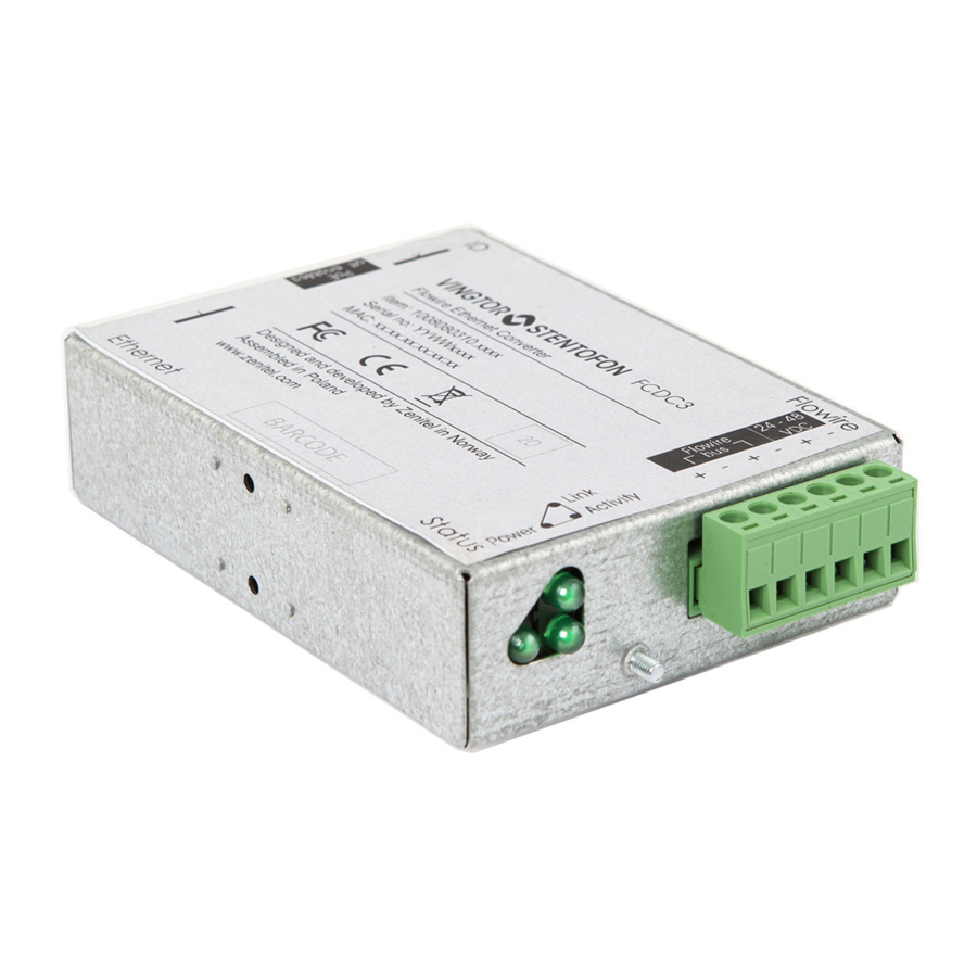
PoE Switch On/Off Reset Flowire Reset FCDC3 Flowire Ethernet Converter Item: 1008080310.xxxx Serial no: YYWWxxxx MAC: xx:xx:xx:xx:xx:xx Designed and developed by Zenitel Norway Assembled in Poland www.zenitel.com Ethernet Status 37,5 Ethernet contact Brackets for NS35 rail mount Part of the package (2pcs) -
Page 13: Power Requirements
4.2 Power Requirements A Flowire Converter needs at least 18V to operate, nominal voltage is 24V to 48V, and maximum voltage is 56V. The voltage at the remote Flowire Converter should never drop below half of the PSU’s output voltage. To power a Vingtor-Stentofon IP Intercom Station through its Ethernet port, we recommend at least 40V at the remote site. -
Page 14: Troubleshooting
Troubleshooting 5.1 Power for Stable Connection at Remote Site The minimum voltage at the remote end for PoE is 40VDC. The minimum voltage for the TFIX Ex intercoms and EAPFX Ex access panels is 18VDC. The PoE voltage can be read on the device’s web interface: ●... - Page 15 Select the log levels to log and to display. The Mode dropdown box selects where the log is recorded. If Local is selected the log will be saved in the local memory. If Remote is selected the log will be sent to the syslog server that is set up in Server IP Address. If Both is selected the syslog will be stored locally and sent to the syslog server.
- Page 16 Log shown in a syslog server: Since there is no real time clock in the FCDC3, the timestamp in the device is related to the start-up time of the FCDC3. A100K11958 FCDC3 Flowire Converter Configuration Manual...
-
Page 17: A: Power Consumption & Distances For Typical Cables
A: Power Consumption & Distances for Typical Cables The table below shows theoretical point-to-point distances for different cable types at different levels of power consumption at the remote location. All distances are calculated for 48V output from the PSU. Cable Type Resistance Intercom Intercom... -
Page 18: B: Advanced Configuration
B: Advanced Configuration IP addresses on a Flowire device can be set either by setting a static IP address or having one assigned from a temporary DHCP server. The Flowire device has, by default, DHCP enabled on one of their networking interfaces. B.1 Setting a Static IP Address &... -
Page 19: Network Management Key (Nmk) Configuration
B.2 Network Management Key (NMK) Configuration To set a new NMK password: 1. Log into the Flowire device by entering its IP address in a web browser. 2. Select Advanced Setup > HomePlug > Network password 3. Enter a new password in the Network password field 4. -
Page 20: Cco Settings
B.3 CCo Settings ● Select Advanced Setup > HomePlug In the Flowire web interface, each Flowire unit has a setting for CCo (Central Coordinator). In every Flowire network, there is always one CCo, but this is, by default, automatically selected. If the CCo should fail, another Flowire unit on the network is automatically selected to be CCo. -
Page 21: C: Software Upgrade
C: Software Upgrade C.1 Upgrade via Web Interface on Flowire Device To upgrade software: 1. Select Management > Update Software 2. Click the Choose File button and browse for the new software file 3. Click Update Software The update will take about 2 minutes. When the update is complete the FCDC3 will reboot. A100K11958 FCDC3 Flowire Converter Configuration Manual... -
Page 22: D: Upgrade Fcdc1/Fcdc2, Eapfx, Tfix To Operate With Fcdc3
D: Upgrade FCDC1/FCDC2, EAPFX, TFIX to Operate with FCDC3 In order for the FCDC1, FCDC2, TFIX, or EAPFX to be able to work with the FCDC3, you need to upgrade the software in the Flowire to at least version 4.1.3.13. The procedure is described in the wiki page Flowire Software Upgrade Procedure A100K11958... - Page 23 A100K11958 FCDC3 Flowire Converter Configuration Manual...
- Page 24 Zenitel and its subsidiaries assume no responsibility for any errors that may appear in this publication, or for damages arising from the information therein. VINGTOR-STENTOFON products are developed and marketed by Zenitel. The company’s Quality Assurance System is certified to meet the requirements in NS-EN ISO 9001. Zenitel reserves the right to modify designs and alter specifications without notice.
Need help?
Do you have a question about the Vingtor Stentofon FCDC3 and is the answer not in the manual?
Questions and answers