Advertisement
Quick Links
Item # 1001 xxx xxx
Model # 51759
UL Model # 52-PLM
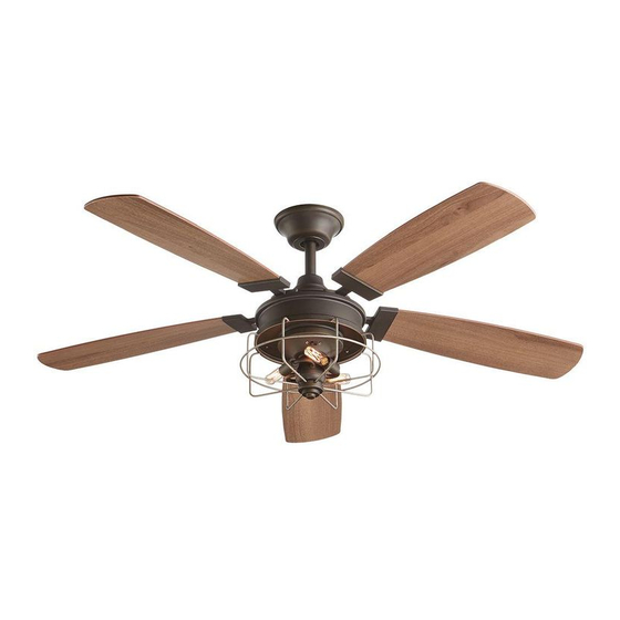
USE AND CARE GUIDE
HALLMAN 52-INCH CEILING FAN
Questions, problems, missing parts? Before returning to the store,
call Home Decorators Collection Customer Service
8 a.m. - 7 p.m., EST, Monday-Friday, 9 a.m. - 6 p.m., EST, Saturday.
1-800-986-3460
HOMEDEPOT.COM/HOMEDECORATORS
THANK YOU
We appreciate the trust and confidence you have placed in Home Decorators Collection through the purchase of this ceiling fan. We strive
to continually create quality products designed to enhance your home. Visit us online to see our full line of products available for your home
improvement needs. Thank you for choosing Home Decorators Collection!
Advertisement

Subscribe to Our Youtube Channel
Related Manuals for Home Decorators Collection HALLMAN 52-PLM


Summary of Contents for Home Decorators Collection HALLMAN 52-PLM
- Page 1 THANK YOU We appreciate the trust and confidence you have placed in Home Decorators Collection through the purchase of this ceiling fan. We strive to continually create quality products designed to enhance your home. Visit us online to see our full line of products available for your home...
-
Page 2: Table Of Contents
Table of Contents Table of Contents ..............2 Assembly ................7 Safety Information ............... 2 Operation ................15 Warranty ................3 Care and Cleaning ............. 16 Pre-Installation ..............3 Troubleshooting ..............16 Installation ................6 Safety Information READ AND SAVE THESE INSTRUCTIONS. WARNING: To reduce the risk of personal injury, do not bend the blade brackets (also referred to as To reduce the risk of electric shock, ensure the electricity has... -
Page 3: Warranty
A certain amount of “wobble” is normal and should not be considered a defect. Servicing performed by unauthorized persons shall render the warranty invalid. There is no other express warranty. Home Decorators Collection hereby disclaims any and all warranties, including but not limited to those of merchantability and fitness for a particular purpose to the extent permitted by law. - Page 4 Pre-Installation (continued) HARDWARE INCLUDED NOTE: Hardware not shown to actual size. Part Description Quantity Part Description Quantity Blade attachment screws Blade bracket hardware (screw and lockwasher) Plastic wire connector...
- Page 5 Pre-Installation (continued) PACKAGE CONTENTS Part Description Quantity Part Description Quantity Slide-on mounting bracket Light kit pan (inside canopy) Light kit plate Ball/downrod assembly Blade bracket Canopy Blade Decorative motor collar cover Light kit decorative cage Fan-motor assembly light kit fitter assembly Edison bulbs (40-Watt, Maximum) IMPORTANT: This product and/or components are governed by one or more of the following U.S.
-
Page 6: Installation
Installation MOUNTING OPTIONS NOTE: You may need a longer downrod to maintain WARNING: To reduce the risk of fire, electric shock, proper blade clearance when installing on a steep, sloped or personal injury, mount the fan to an outlet box ceiling. -
Page 7: Assembly
Assembly - Attaching the Blades Attaching the blades to the blade Fastening the blade assemblies to brackets the motor □ □ Attach a blade (I) to the blade bracket (H) by inserting the Fasten the blade bracket (H) to the fan-motor assembly (E) by screws (AA) into the holes in the blade and through the blade aligning the holes from blade bracket with the screw holes on bracket (H). - Page 8 Assembly - Standard Ceiling Mount Preparation for standard mounting Routing the wires □ □ Remove the canopy ring (FF) from the canopy (C) by turning Route the wires exiting at the top of the fan-motor the ring counterclockwise until it unlocks. assembly (E) through the canopy ring (FF).
- Page 9 Assembly - Hanging the Fan Attaching the fan to the electrical Hanging the fan □ Carefully lift the fan-motor assembly (E) up to the slide-on mounting bracket (A). WARNING: To reduce the risk of fire, electric shock, or other □ personal injury, mount the fan to an outlet box or supporting Seat the hanger ball portion of the ball/downrod assembly (B) system marked “Acceptable for fan support of 35 lbs.
- Page 10 Assembly - Hanging the Fan (continued) Setting the code on the remote control and receiver NOTE: The frequencies on your receiver and hand unit have been preset at the factory. Before installing the receiver, make sure the dip switches on the receiver and hand unit are set to the same frequency.
- Page 11 Assembly - Hanging the Fan (continued) Wiring the receiver to the household Wiring the fan to the receiver wiring WARNING: To avoid possible electrical shock, turn the IMPORTANT: Use the wire connecting nuts (BB) supplied with electricity off at the main fuse box before wiring. If you your fan.
- Page 12 Assembly - Hanging the Fan (continued) Mounting the fan-motor assembly Wrapping the extra wire (standard mount) WARNING: When using the standard ball/downrod mounting, the NOTE: Follow this step ONLY if you did not cut the extra length off tab in the ring at the bottom of the mounting bracket must rest in from the wires coming from the ceiling fan to the receiver.
- Page 13 Assembly - Attaching the Light Attaching the light kit pan □ Remove one screw (NN) from the black bracket below fan motor assembly (E), loosen but do not remove the other two screws. □ Push the light kit pan (F) up to the fan motor assembly (E) so that the two loosened screw heads fit into the keyhole slots.
- Page 14 Assembly - Attaching the Light (continued) Attaching the light kit plate □ Remove one screw (PP) from the light kit pan (F), and loosen, but do not remove the other two screws. □ Push the light kit plate (G) up to the light kit pan so the two loosened screw heads fit into the keyholes slots.
-
Page 15: Operation
Operating Your Fan and Remote Control A. Warm weather Remote Control - Your fan is equipped with a remote control to operate the speed and lights of your new ceiling fan. Speed setting for warm or cool weather depends on factors such as the room size, ceiling height, number of fans and so on. -
Page 16: Care And Cleaning
Care and Cleaning WARNING: Make sure the power is off before cleaning your fan. □ Because of the fan’s natural movement, some connections may become loose. Check the support connections, brackets, and blade attachments twice a year. Make sure they are secure. It is not necessary to remove the fan from the ceiling. □... - Page 17 This equipment has been tested and found to comply with the limits for a Class B digital device, pursuant to Part 15 of the FCC Rules. These limits are designed to provide reasonable protection against harmful interference in a residential installation. This equipment generates, uses and can radiate radio frequency energy and, if not installed and used in accordance with the instructions, may cause harmful interference to radio communications.
Need help?
Do you have a question about the HALLMAN 52-PLM and is the answer not in the manual?
Questions and answers