Table of Contents
Advertisement
4.1 Instructions
4.2 Cleaning the appliance
4.3 Removing the door
4.4 Cleaning the door glazing
4.5 Vapor Clean (on some models only)
4.6 Pyrolytic (on some models only)
4.7 Extraordinary maintenance
We advise you to read this manual carefully, which contains all the instructions for
maintaining the appliance's aesthetic and functional qualities.
For further information on the product: www.smeg.com
Contents
79
79
83
83
84
84
84
85
86
86
87
87
88
89
91
91
92
93
96
97
105
107
110
113
116
117
117
117
118
119
122
125
127
77
Advertisement
Table of Contents

Related Manuals for Smeg Portofino


Summary of Contents for Smeg Portofino
-
Page 1: Table Of Contents
4.5 Vapor Clean (on some models only) 4.6 Pyrolytic (on some models only) 4.7 Extraordinary maintenance We advise you to read this manual carefully, which contains all the instructions for maintaining the appliance’s aesthetic and functional qualities. For further information on the product: www.smeg.com... - Page 2 Contents 5 Installation 5.1 Gas connection 5.2 Adaptation to different types of gas 5.3 Positioning 5.4 Electrical connection 5.5 Instructions for the installer...
-
Page 3: Instructions
Instructions 1 Instructions • Keep children under the age of eight at a safe distance unless 1.1 General safety instructions they are constantly supervised. • Keep children under the age of 8 Risk of personal injury away from the appliance when it •... - Page 4 Instructions • The cooking process must always • Do not use aerosols in the vicinity be monitored. A short cooking of this appliance whilst it is in use. process must be continuously • Switch off the appliance monitored. immediately after use. •...
- Page 5 Instructions Risk of damaging the appliance • Do not spray any spray products near the oven. • Do not use abrasive or corrosive • Do not use plastic cookware or detergents (e.g. scouring containers when cooking food. powders, stain removers and metallic sponges) on glass parts.
- Page 6 Instructions • If any liquid does boil over or spill, • Never use the oven door to lever remove the excess from the hob. the appliance into place when fitting. • Take care not to spill acid substances such as lemon juice or •...
-
Page 7: Appliance Purpose
Instructions • The hoses should not come into For this appliance contact with moving parts and • Ensure that the appliance is should not be crushed in any way. switched off before replacing the • If required, use a pressure bulb. -
Page 8: This User Manual
Instructions 1.4 This user manual • Deliver the appliance to the appropriate recycling centre for electrical and This user manual is an integral part of the electronic equipment waste, or return it to appliance and must therefore be kept in its the retailer when purchasing an entirety and within the user’s reach for the equivalent product, on a one for one... -
Page 9: How To Read The User Manual
Instructions 1.7 How to read the user manual This user manual uses the following reading conventions: Instructions General information on this user manual, on safety and final disposal. Description Description of the appliance and its accessories. Information on the use of the appliance and its accessories, cooking advice. -
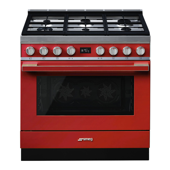
Page 10: Description
Description 2 Description 2.1 General Description 1 Cooking hob 5 Door 2 Control panel 6 Fan 3 Oven light 7 Storage compartment 4 Seal Rack/tray support frames... -
Page 11: Cooking Hob
Description 2.2 Cooking hob AUX = Auxiliary R = Rapid SR = Semi-rapid DUAL = Ultra-rapid 2.3 Control panel 1 Hob burner knobs Return the knobs to the position to turn Used for lighting and adjusting the hob off the burners. burners. -
Page 12: Other Parts
Description 3 Display Interior lighting Displays the current time, the selected The appliance’s interior lighting comes on: cooking temperature and function and any • When the door is opened. time set. • When any function is selected, apart 4 Function knob from the functions This knob allows you to turn the appliance... -
Page 13: Available Accessories
Description 2.5 Available accessories Oven tray WOK ring Useful for collecting fat from foods placed Useful when using a wok. on the rack above. Deep tray Tray rack Useful for collecting fat from foods placed To be placed over the top of the oven tray; on the rack above and for cooking pies, for cooking foods which may drip. - Page 14 Description Rack Some models are not provided with all accessories. The accessories intended to come into contact with food are made of materials that comply with the provisions of current legislation. Useful for supporting containers with food during cooking. Supplied and optional accessories can be requested to Authorised Rotisserie (on some models only) Assistance Centres.
-
Page 15: Use
3 Use Improper use Risk of damage to surfaces 3.1 Instructions High temperature inside the oven • Do not cover the bottom of the oven during use cavity with aluminium or tin foil sheets. Danger of burns • If you wish to use greaseproof paper, place it so that it will not interfere with the •... -
Page 16: First Use
Malfunctions High temperature inside the oven during use Any of the following indicate a malfunction and you should contact a service centre. Danger of fire or explosion • Yellowing of the burner plate. • Do not spray any spray products near •... -
Page 17: Using The Accessories
3.3 Using the accessories Racks and trays Racks and trays have to be inserted into the Ring reducers side guides until they come to a complete The ring reducers must be placed on the stop. hob grids. Make sure they are placed The mechanical safety locks that prevent the properly. - Page 18 Rotisserie (on some models only) 3. Prepare the rotisserie rod with the food using the clip forks provided. The clip 1. Insert the 4 supplied bushings in the 4 forks can be tightened using the corner holes of the deep tray and screw fastening screws.
- Page 19 5. Place the tray on the first runner (see 7. To activate the rotisserie, turn the function “General Description”). knob to select the 6. Insert the tip of the rod in the rotisserie function and use the temperature knob to motor housing on the left of the rear wall set a cooking temperature.
-
Page 20: Using The Hob
3.4 Using the hob Correct positioning of the flame- spreader crowns and burner caps All the appliance’s control and monitoring devices are located together on the front Before lighting the hob burners, make sure panel. The burner controlled by each knob that the flame-spreader crowns are is shown next to the knob. -
Page 21: Using The Oven
Correct positioning of the hob grids 3.5 Using the oven Before lighting the hob burners, make sure Display that the grids are correctly positioned on the hob. Bear in mind that: • Each grid has its own position on the hob. - Page 22 Operating modes Each time the temperature knob is pressed during a function, the parameters will be Stand-by: When no function is selected, the cycled through in the following order. display shows the current time Temperature Minute minder timer duration Function duration Programmed cooking duration (if timed cooking has been selected) Time display...
- Page 23 Setting the time Cooking functions When using the appliance for the first time, or after a power failure, the symbol will flash on the display. To be able to start any cooking function, the current time must be set. 1. Turn the temperature knob to set the displayed time (keep the knob turned to produce a faster increase or decrease).
- Page 24 Functions list Grill The heat coming from the grill element gives perfect grilling results This function is particularly suitable above all for thin and medium for cooking on a single shelf with thickness meat and, in combination low energy consumption. with the rotisserie (where fitted), Ideal for cooking meat, fish and gives the food an even browning at...
- Page 25 Timer Fan + lower element The combination of the fan with just This function only activates the the lower heating element allows buzzer, without stopping cooking. cooking to be completed more rapidly. This system is The minute minder can be recommended for sterilising or for activated both during cooking and finishing off the cooking of foods...
- Page 26 4. To deactivate the buzzer, press or turn 2. Turn the temperature knob right or left to one of the two knobs. set the cooking duration from 00:01 to 12:59. Keep the knob turned to produce 5. To select a further minute minder, turn the a faster increase or decrease.
- Page 27 5. To deactivate the buzzer, press or turn Programmed cooking one of the two knobs or open the door. Programmed cooking is the function which allows cooking to To deactivate the buzzer and be stopped at an established time select a further timed cooking, turn depending on the time set by the the temperature knob to the right.
- Page 28 3. Press the temperature knob a fourth time. 5. At the end of cooking, The indicator light flashes. Turn the shown on the display and a buzzer knob right or left to set the cooking end sounds. time. 4. After a few seconds the indicator lights stop flashing.
-
Page 29: Cooking Advice
Modifying the data set during 3.6 Cooking advice programmed cooking General advice After modifying the cooking • Use a fan assisted function to achieve duration, the end of cooking time consistent cooking at several levels. must be re-set. • It is not possible to shorten cooking times by increasing the temperature (the food During operation, it is possible to modify could be overcooked on the outside and... - Page 30 Advice for cooking desserts/pastries and • To defrost meat, use the rack placed on biscuits the second level and a tray on the first level. In this way, the liquid from the • Use dark metal moulds: They help to defrosting food drains away from the absorb the heat better.
-
Page 31: Special Functions
3.7 Special functions Proving Defrost by time When using the proving function the temperature cannot be altered. 1. Place the food inside the oven. 2. Press and turn the function knob to select For successful proving, a container the defrost by time function of water should be placed in the 3. - Page 32 Sabbath After activating the Sabbath function the settings cannot be altered. Any action on the knobs will produce no effect; only the function knob remains active to allow the appliance to be turned off. This function allows food to be 1.
- Page 33 5. Turn the temperature knob to select the Defrost by weight weight (in grams) of the food to defrost. 6. Press the function knob to confirm the parameters and start defrosting. 7. At the end, is displayed and a buzzer sounds. 8.
-
Page 34: Automatic Programs
3.8 Automatic programs 5. When preheating has finished, will flash. Introduce the food and then press the function knob to start cooking. 6. At the end, is displayed and a buzzer sounds. 7. To deactivate the buzzer, press or turn one of the two knobs or open the door. - Page 35 Automatic programs table MEAT (01 - 05) Weight Temperature Time Subcategory Level Function (°C) (minutes) Roast beef 1300 (cooked medium) 02 Roast pork 03 Lamb (cooked medium) 2000 04 Veal 1000 05 Roast chicken (whole) 1000 FISH (06 - 07) Weight Temperature Time...
- Page 36 DESSERTS/PASTRIES (11 - 13) Weight Temperature Time Subcategory Level Function (°C) (minutes) 11 Biscuits 12 Muffins 13 Tart 1000 BREAD - PIZZA - PASTA (14 - 20) Weight Temperature Time Subcategory Level Function (°C) (minutes) 14 Leavened bread (loaf) 1000 15 Pan baked pizza 1000 16 Stone baked pizza...
-
Page 37: Secondary Menu 113
3.9 Secondary menu Child lock mode The appliance also has a drop-down This mode allows the appliance to lock the secondary menu allowing the user to: controls automatically after one minute of normal operation without any intervention • Activate or deactivate the Child lock. from the user. - Page 38 To release the lock temporarily during Showroom mode (for exhibitors only) cooking, hold the temperature knob down This mode allows the appliance to for 5 seconds. One minute after the last deactivate all heating elements, while setting the lock will become active again. keeping the control panel active.
- Page 39 Low power (Eco-logic) mode: Keep Warm mode This mode allows the appliance to limit the This mode allows the appliance to keep power used. cooked food warm (at low temperatures) for around an hour after cooking finishes Suitable for simultaneous use with further with a cooking cycle for which a duration home appliances.
-
Page 40: Using The Storage Compartment 116
3.10 Using the storage compartment Eco-light mode There is a storage compartment located at For greater energy savings, the light is the bottom of the cooker; this can be used automatically deactivated one minute from to store pans or metal objects required for the start of cooking. - Page 41 Cleaning and maintenance 4 Cleaning and maintenance Cleaning the hob 1. Pour some non-abrasive detergent on a 4.1 Instructions damp cloth and wipe the surfaces. 2. Rinse thoroughly. Improper use Risk of damage to surfaces 3. Dry with a soft cloth or a microfibre cloth. Cleaning the hob grids, flame-spreader •...
-
Page 42: Cleaning And Maintenance
Cleaning and maintenance Cleaning the igniters and thermocouples For easier cleaning, we recommend removing: • If necessary, clean the igniters and • The door thermocouples with a damp cloth. • The rack/tray support frames • If there is any dry residue, remove it with a toothpick or needle. - Page 43 Cleaning and maintenance 2. Grasp the door on both sides with both Removing the internal glass panes hands, lift it forming an angle of around For easier cleaning the internal glass panes 30° and remove it. of the door can be removed. 1.
- Page 44 Cleaning and maintenance 3. Remove the intermediate glass pane by Removing racks/trays support frames lifting it upwards. Removing the rack/tray support frames enables the sides to be cleaned more easily. To remove the rack/tray support frames: • Pull the frame towards the inside of the oven to unhook it from its groove A, then slide it out of the seats B at the back.
- Page 45 Cleaning and maintenance Manual deactivation of the door lock 1. Move the door lock lever to the right until lever (pyrolytic models only) it stops. Improper use Danger of burns • The following operations must always be performed with the appliance cold and switched off.
- Page 46 Cleaning and maintenance 4.5 Vapor Clean (on some models Cleaning the top section (not on pyrolytic models) only) The oven cavity is fitted with a tilting heating Vapor Clean is an assisted element which facilitates cleaning the top cleaning procedure which part (roof) of the oven.
- Page 47 Cleaning and maintenance • Pour approximately 40 cc of water into Vapor Clean cycle setting the tray. Make sure it does not overflow If the internal temperature is out of the cavity. greater than that required for the Vapor Clean cycle, the cycle will be stopped immediately and the message will appear...
- Page 48 Cleaning and maintenance Programmed Vapor Clean cycle End of the Vapor Clean cycle Like for the normal cooking functions, it is At the end, is displayed and a also possible to set an end time for the buzzer sounds. Vapor Clean function. 1.
- Page 49 Cleaning and maintenance 4.6 Pyrolytic (on some models only) Pyrolytic function setting 1. Select one of the cleaning functions Pyrolytic cleaning is an automatic high-temperature cleaning with the function knob. procedure which causes dirt to 2. Turn the temperature knob to the right or dissolve.
- Page 50 Cleaning and maintenance 2. Two minutes after the pyrolytic cycle has If the pyrolytic cycle gives started the door is locked (the door lock unsatisfactory results at minimum duration, it is recommended to set indicator light comes on) by a a longer time for successive device that prevents the door from being cleaning cycles.
- Page 51 Cleaning and maintenance 4.7 Extraordinary maintenance 4. Slide out and remove the light bulb. Replacing the internal light bulb Live parts Danger of electrocution • Unplug the appliance. The oven is fitted with a 40W light Do not touch the halogen light bulb.
- Page 52 Cleaning and maintenance Removing and installing the door seal What to do if... (not on pyrolytic models) The appliance is not working properly: To remove the seal: • The switch is defective: check the fuse • Unhook the clips located in the 4 corners box to see whether the switch is in and in the centre, then pull the seal working order.
- Page 53 Cleaning and maintenance The display is completely off: (pyrolytic models only) After the (pyrolytic) automatic cleaning cycle it is • Check the mains power supply. not possible to select a function: • Check whether an omnipolar switch • Verify whether the door lock has upstream of the appliance supply line is deactivated.
-
Page 54: Installation
Installation 5 Installation Connection with a rubber hose Verify that all following conditions are met: 5.1 Gas connection • the hose is fixed to the hose connection with safety clamps; Gas leak • no part of the hose is in contact with hot Danger of explosion walls (max. - Page 55 Installation After having tightened the hose Carefully screw the connector 3 to the gas connector(s), push the gas hose 6 onto the connector 1 of the appliance, placing the hose connector and secure it with the clamp 5 seal 2 between them. that is compliant with the standard in force.
- Page 56 Installation Connection with a steel hose with conical Gas connection extension cord fitting (pyrolytic models only) Make the connection to the gas mains For pyrolytic models, the supplied gas using a continuous wall steel hose whose connection extension cord must be specifications comply with the applicable installed: standard.
- Page 57 Installation 3. Carefully screw the connector 3 to the 4. Carefully screw the assembled gas extension cord 1 of the appliance, extension cord C to the gas connector placing the seal 2 between them. D of the appliance, placing the seal 2 between them.
- Page 58 Installation Room ventilation When the job is complete, the installer must issue a certificate of conformity. The appliance should be installed in rooms that have a permanent air supply in accordance with the standards in force. The room where the appliance is installed must have enough air flow for the regular combustion of gas and the necessary air change in the room itself.
- Page 59 Installation 5.2 Adaptation to different types of Adjusting the minimum setting for natural or town gas In case of operation with other types of gas, Light the burner and turn it to the minimum the burner nozzles must be changed and position.
- Page 60 Installation Adjusting the minimum setting for LPG Dimensions Position of gas and electrical connections. Tighten the screw located at the side of the tap rod clockwise all the way. Following adjustment to a gas other than the one originally set in the factory, replace the gas setting label on the appliance with the one corresponding to the new gas.
- Page 61 Installation Gas types and Countries Gas types IT GB-IE FR-BE DE 1 Natural Gas G20 20 mbar • • • • • • • • • • G20/25 20/25 mbar • 2 Natural Gas G20 25 mbar • 3 Natural Gas G25.1 G25.1 25 mbar •...
- Page 62 Installation Burner and nozzle characteristics tables 1 Natural gas G20 – 20 mbar Rated heating capacity (kW) Nozzle diameter (1/100 mm) Pre-chamber (printed on nozzle) (H9) (F3) Reduced flow rate (W) 1200 2 Natural gas G20 – 25 mbar Rated heating capacity (kW) Nozzle diameter (1/100 mm) Pre-chamber (printed on nozzle) (H8)
- Page 63 Installation 7 LPG G30/G31 – 37 mbar Rated heating capacity (kW) Nozzle diameter (1/100 mm) Pre-chamber (printed on nozzle) Reduced flow rate (W) 1500 Rated flow rate G30 (g/h) Rated flow rate G31 (g/h) 8 LPG G30/G31 – 50 mbar Rated heating capacity (kW) Nozzle diameter (1/100 mm) Pre-chamber (printed on nozzle)
- Page 64 Installation 5.3 Positioning Dimensions Heavy appliance Crushing hazard • Position the appliance into the cabinet cutout with the help of a second person. Pressure on the door Risk of damage to the appliance • Never use the oven door to lever the appliance into place when fitting.
- Page 65 Installation General information This appliance may be installed next to walls, one of which must be higher than the worktop, at a minimum distance of X mm from the side of the appliance, as shown in figures A and C relative to the installation classes.
- Page 66 Installation Positioning and levelling Fastening to the wall Heavy appliance The anti-tip devices must be installed in order to prevent the Risk of damage to the appliance appliance from tipping over. • Insert the front feet first and then the rear 1.
- Page 67 Installation 3. Assemble the fastening bracket. 5. Align the base of the fastening bracket with the ground and tighten the screws to fix the measurements. 6. Use 50 mm for the distance from the side of the appliance to the bracket holes. 4.
- Page 68 Installation 7. Move the bracket onto the wall and Fastening to the ground mark the position of the holes to be If fastening to the ground, contact drilled in the wall. the nearest Authorised Service Centre Installing the front skirting The front skirting must always be positioned and secured correctly on the appliance.
- Page 69 Installation 2. Position the front skirting at the bottom of Installing the side skirting the appliance and line up the side holes After installing the front skirting, the side of the front skirting with the holes on the skirting can be fastened correctly to the base of the appliance.
- Page 70 Installation 4. Line up the hole on the side skirting with Assembling the upstand the rear hole on the base of the The supplied upstand is an integral appliance. part of the product and it is recommended to fasten it to the appliance prior to installation.
-
Page 71: Electrical Connection
Installation 5.4 Electrical connection The appliance can work in the following modes: Power voltage Pyrolytic model Danger of electrocution • 220-240 V 1N~ • Have the electrical connection performed by authorised technical personnel. • Use personal protective equipment. 3 x 2.5 mm² three-core cable. •... - Page 72 Installation Access to the terminal board (pyrolytic 3. Proceed with installation of the power models only) supply cable. To connect the power supply cable, you must access the terminal board on the rear casing: 1. Remove the screws fastening the plate to the rear casing.
-
Page 73: Instructions For The Installer
Installation The appliance can work in the following • Do not try to unscrew or force the modes: threaded elbow of the fitting. You may damage this part of the appliance, which Multifunction model may void the manufacturer’s warranty. • 220-240 V 1N~ •...
Need help?
Do you have a question about the Portofino and is the answer not in the manual?
Questions and answers