Table of Contents
Advertisement
Quick Links
Table of Contents
1 General Information ........................................................................................................ 1
1.1 Safety Messages ...................................................................................................... 1
1.2 Validity ....................................................................................................................... 2
1.3 Safety Precautions ................................................................................................... 2
2 Product Overview ............................................................................................................ 5
2.1 Components of PV Grid-Connected System .......................................................... 5
2.2 Schematic Diagram .................................................................................................. 6
2.3 Appearance of Inverter ............................................................................................. 6
2.4 Weights and Dimensions of Inverter........................................................................ 7
2.5 Specifications ............................................................................................................ 8
3 Unpacking and Storage................................................................................................. 11
3.1 Unpacking Inspection ............................................................................................. 11
3.2 Storage .................................................................................................................... 11
4 Installation...................................................................................................................... 12
4.1 Mounting Location .................................................................................................. 12
4.2 Mounting the Inverter ............................................................................................. 13
4.2.1 Clearance ...................................................................................................... 13
4.2.2 Installation Procedure ................................................................................... 13
5 Electrical Connection .................................................................................................... 15
5.1 Safety Precautions ................................................................................................. 15
5.2 Electrical Connection Diagram .............................................................................. 16
5.3 Cable Requirements ............................................................................................... 17
5.4 DC Connection........................................................................................................ 18
5.5 AC Connection ........................................................................................................ 20
5.6 Second Protective Earth Connection .................................................................... 21
5.7 Connection of Anti-Backflow Meter (Optional) ...................................................... 22
6 Installing the Communication Module .......................................................................... 24
7 Operation ....................................................................................................................... 26
7.1 Switching On ........................................................................................................... 26
7.2 Switching Off ........................................................................................................... 26
7.3 LED Indicator Lights ............................................................................................... 27
8 Monitoring ...................................................................................................................... 28
8.1 Professional Edition App ........................................................................................ 28
8.1.1 Software Installation ...................................................................................... 28
8.1.2 Registration & Login...................................................................................... 28
8.1.3 Create Plant................................................................................................... 30
8.2 Home Edition App ................................................................................................... 33
8.2.1 Software Installation ...................................................................................... 33
8.2.2 Registration & Login...................................................................................... 33
8.2.3 Create Plant................................................................................................... 34
9 Troubleshooting for Fault Messages Displayed on APP ............................................. 36
Advertisement
Table of Contents

Related Manuals for Epcom EPIG7K

Summary of Contents for Epcom EPIG7K
-
Page 1: Table Of Contents
Table of Contents 1 General Information ......................1 1.1 Safety Messages ...................... 1 1.2 Validity ........................2 1.3 Safety Precautions ....................2 2 Product Overview ......................5 2.1 Components of PV Grid-Connected System ............5 2.2 Schematic Diagram ....................6 2.3 Appearance of Inverter ..................... -
Page 2: General Information
1 General Information 1.1 Safety Messages Read the manual carefully to become familiar with the equipment before trying to install, operate, service or maintain it. The following safety messages may appear throughout this manual or on the equipment to warn of potential hazards. DANGER DANGER indicates a hazardous situation which, if not avoided, will result in death or serious injury. -
Page 3: Validity
Caution, risk of electric Warning of danger shock Danger alert of electric shock. Energy storage Caution, hot surface timed discharge (time to be indicated adjacent to the symbol) 1.2 Validity This manual is valid for the following residential single phase on-grid PV inverters (hereinafter referred to as inverter): 2 kW / 2.5 kW / 3 kW / 3 kW –... - Page 4 DANGER! High voltage may result in death or serious burns! ● Operations on the inverter must be performed by qualified personnel. ● PV arrays exposed to light may generate dangerous voltage. ● Do not touch the electriferous modules in the PV system while the inverter is running.
- Page 5 NOTICE! Contact or improper operation on printed circuit board or other electrostatic sensitive components may result in damage to the components. ● Avoid unnecessary contacts with circuit boards. ● Comply with electrostatic protection standards, wear an antistatic wrist strap. When installing PV arrays during the day, opaque material should be used to cover the solar battery arrays, otherwise, the solar array will generate high voltage under sunlight.
-
Page 6: Product Overview
2 Product Overview 2.1 Components of PV Grid-Connected System PV grid-connected system consists of PV modules, PV grid-connected inverters, metering device and power distribution system. The solar energy is converted into DC via PV modules, and then the DC is converted into sinusoidal AC which has the same frequency and phase as the utility grid and fed into the utility grid via inverters. -
Page 7: Schematic Diagram
2.2 Schematic Diagram Inverter MPPT1 DC Switch DC BUS (DC/AC) LCL Filter (DC/DC) Relay GFCI MPPT2 (DC/DC) Dual DSP/MCU Insulation Detection RS485/GPRS/WiFi Note: The above figure is the schematic diagram of 3 kW-D / 3.68 kW / 4 kW / 4.6 kW / 5 kW / 6 kW / 7kW inverters. -
Page 8: Weights And Dimensions Of Inverter
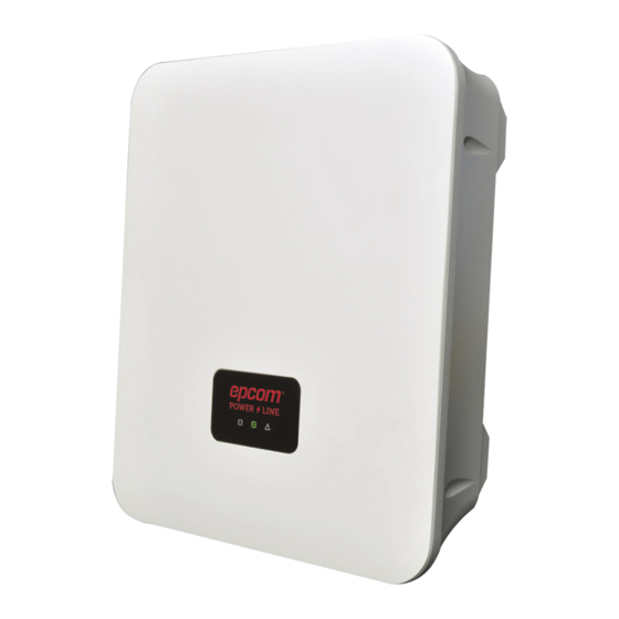
Description Explanation To display the inverter running state / ① LED display panel communication status ② DC input terminals To connect inverter to PV modules ③ DC switch To directly control DC input On / Off To connect Wi-Fi or other communication ④... -
Page 9: Specifications
Dimensions of 3 kW-D / 3.68 kW / 4 kW / 4.6 kW / 5 kW / 6 kW / 7kW inverter: 2.5 Specifications 3.68 Model kW - Input (DC) Max. input 3250 3900 power (W) Max. input 600 V voltage Start-up 120 V... - Page 10 4900 Rated output 2500 3000 5000 power (W) 21.3 Max. (AUS) 10.9 17.4 26.1 30.5 output 13 A 21.8 current (EUR) Rated output 230 Vac voltage On-grid voltage 180 – 280 Vac range Rated 50/60 Hz frequency On-grid frequency 45 – 55 Hz /55 – 65 Hz range <...
- Page 11 Communic RS485*2, Wi-Fi / Ethernet ation Dimension s (W×D×H) 308 × 116.5 × 353 370 × 126.5 × 420 (mm) Weight < 9 kg < 11.5 kg Operating temperatur - 25℃ ~ + 60℃ (> 45℃ downgrading) Relative 0% ~ 100% humidity 4000 m (>...
-
Page 12: Unpacking And Storage
3 Unpacking and Storage 3.1 Unpacking Inspection Although the product has been rigorously tested and inspected before delivery, damage may still occur during transport. Check that the delivery is complete, check the packaging and the inverter for externally visible damage, and inspect the package contents upon receipt. -
Page 13: Installation
4 Installation 4.1 Mounting Location DANGER! Danger to life due to fire or explosion! ● Do not mount the inverter on flammable construction materials. ● Do not install the inverter in areas where highly flammable materials are stored. ● Do not install the inverter in areas with a risk of explosion. In order to ensure that the inverter operates properly, the installation environment and requirements are as follows: ... -
Page 14: Mounting The Inverter
4.2 Mounting the Inverter 4.2.1 Clearance Note: Only install the inverter vertically or tilted backwards no more than 15 degrees. Do not tilt or install the inverter horizontally. The wiring terminal should be downwards. In order to maintain sufficient ventilation, when installing the inverter a minimum clearance of 30 cm at the sides and top must be maintained. - Page 15 Attach the inverter to the wall mounting bracket. Screw the inverter to the wall mounting bracket on both sides using the M5 screws provided. Tighten the screws and make sure that they are securely in place. The Wall mounting bracket reserved a padlock hole to prevent the inverter from being stolen.
-
Page 16: Electrical Connection
5 Electrical Connection 5.1 Safety Precautions DANGER! Improper wiring may result in fatal injury to operator or unrecoverable damage to the inverter. Only qualified personnel can perform the wiring operation. The breakers on the AC/DC sides of the inverter must be disconnected and the warning marks must be set before wiring. -
Page 17: Electrical Connection Diagram
5.2 Electrical Connection Diagram Electrical connection of the inverter includes connection on the DC side, connection on the AC side, communication modules connection, second protective earth connection and connection of anti-backflow meter. Item Description 2 kW / 2.5 kW / 3 kW inverters are featured with single MPPT and single string input. -
Page 18: Cable Requirements
CAUTION Multiple inverters can be connected to a grid-connected grid, but it should not exceed 10 units. Otherwise, the inverter may not operate normally. CAUTION It is forbidden to connect the load between the inverter and the circuit breaker. 5.3 Cable Requirements Only waterproof terminals are included in scope of delivery. -
Page 19: Dc Connection
5.4 DC Connection DANGER ! Before electrical connection, cover the PV battery modules with light-proof material and disconnect the circuit breaker on the DC side. WARNING ! This product is a non-isolated inverter, the positive and negative electrodes of the PV module cannot be grounded, otherwise it will emit PV ISO Fault. - Page 20 Positive (+) Input Terminal and Die Negative (-) Input Terminal and Die Wiring on the DC side Strip the DC cable insulation about 8 mm to expose the copper wire. Insert the cable copper wire into the metal core of the connector and tighten it with a crimper (As shown in the figure below).
-
Page 21: Ac Connection
5.5 AC Connection WARNING ! Ensure that electrical connections are in compliance with the local national and local standards. WARNING ! The uncharged metal parts in PV power generation systems consist of PV module bracket, the metal case of the inverter, which should be grounded reliably. -
Page 22: Second Protective Earth Connection
5.6 Second Protective Earth Connection CAUTION The PE point at the AC output port is used only as a PE equipotential point, and cannot substitute for the PE point on the enclosure. DANGER ! Do not connect the neutral wire to the enclosure as a PE cable. Otherwise, electric shocks could occur. -
Page 23: Connection Of Anti-Backflow Meter (Optional)
5.7 Connection of Anti-Backflow Meter (Optional) The inverter equipped with anti-backflow function can perform power regulation and prevent feeding energy into the grid. Before using the anti-backflow function, the user should read the instructions carefully and correctly connect the cables as shown in the figure. - Page 24 Definition and wiring of the anti-backflow meter terminal are shown below. Definition Description Live No special requirements Live No special requirements Neutral No special requirements Neutral No special requirements White wire Black wire No special requirements No special requirements As shown in the above figure, the anti-backflow meter terminals 7 & 8 are separately connected to the pin 8 and pin 6 of COM2.
-
Page 25: Installing The Communication Module
6 Installing the Communication Module Insert the Wi-Fi module into the COM1 communication interface at the bottom of the inverter and tighten the fastening screw. The RJ45 plug for electric meter communication and digital input is inserted into the COM2 connector, the RJ45 plug for DRM communication is inserted into the COM3 connector (only for Australian configuration). - Page 26 CAUTION Make sure the waterproof cover is tightly secured when external network cables are not connected to the COM2 and COM3 interfaces. Please install the waterproof terminal to ensure the waterproof performance of the inverter when external network cables are connected to the COM2 and COM3 interfaces.
-
Page 27: Operation
7 Operation 7.1 Switching On Follow the above instructions to complete the connection of PV arrays and wiring on the AC/DC side of the inverter. Before turning on the inverter, verify the following items: The inverter is installed correctly and securely. The installation environment is convenient for operation and maintenance. -
Page 28: Led Indicator Lights
7.3 LED Indicator Lights The current status of operating and communications of the inverter can be viewed via the three LED indicator lights on the panel (as shown in following table). Display Status Explanation Illuminated Communication is normal Extinguish Communication module is disconnected Inverter is in grid-connected power Illuminated generation status... -
Page 29: Monitoring
8 Monitoring This series of inverters doesn’t have an LCD display screen, therefore the wireless communication module is required to view the running state. Please refer to section 6 for the installation of wireless communication module. After installing the Wi-Fi communication module, users can download a mobile App to monitor the running state of the whole PV system. - Page 30 Login: Click on [Log in] in the App home page, and enter your email and password. ~ 29 ~...
-
Page 31: Create Plant
8.1.3 Create Plant Method 1: Click on [Add] in the App home page, and click the [Plant] icon from the pop-up menu, then scan the serial number of the stick logger. Method 2: click the [Plant] icon first to enter the plant list, then click [+] in the upper right corner to add the plant, then scan the serial number of the stick logger. - Page 32 Note: If fail to scan by method 1 and method 2, you can manually enter the serial number. Edit the plant information Enter the interface of plant information after successfully scanning the serial number or clicking on [No Device]. Confirm your plant location.
- Page 33 Enter the plant name. It is suggested to create a plant name like “location + name + capacity”, then click on [Done]. Then the plant you added is shown on the homepage. ~ 32 ~...
-
Page 34: Home Edition App
8.2 Home Edition App Home edition APP is mainly used for residential PV system. It collects power generation information and operation information to enable users to obtain the running status information of the inverter in time. 8.2.1 Software Installation Search “solarman” in Apple Store to download the App for iPhones, Search “solarman” in Google Play to download the App for Android phones. -
Page 35: Create Plant
8.2.3 Create Plant After login, click [+] in the upper right corner and follow the on-screen instructions. Then scan the serial number of the stick logger, or manually enter the serial number. Edit Plant Information Confirm your plant location. GPS function will automatically locate the plant site. If you want to modify the location, click the [map] icon , and then manually enter the plant address. - Page 36 Enter the plant name. It is suggested to create a plant name like “location + name + capacity”, then click on [Done]. Then the plant you added is listed on the homepage. ~ 35 ~...
-
Page 37: Troubleshooting For Fault Messages Displayed On App
9 Troubleshooting for Fault Messages Displayed on Fault Messages Description Corrective Action Grid overvoltage Voltage on AC side Check if the grid voltage is within the / undervoltage exceeds the allowable allowable range. Contact the local range operation and maintenance personnel for any help.
Need help?
Do you have a question about the EPIG7K and is the answer not in the manual?
Questions and answers