Table of Contents

Subscribe to Our Youtube Channel
Related Manuals for BOSER Technology HS-6238

Summary of Contents for BOSER Technology HS-6238
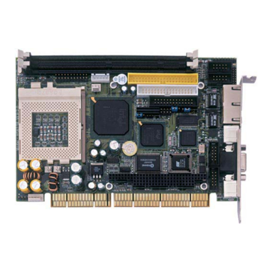
- Page 1 HS-6238 Celeron™/Coppermine™/Tualatin™ Industrial Single Board Computer •Half Size•All-in-One•CRT/Panel•133MHz FSB• •CompactFlash•ATA/33/66/100•Dual LAN• •Audio•4COM•PC/104•IrDA•USB•WDT• •PCI-ISA Bus Industrial Single Board Computer•...
- Page 2 Copyright Disclaimers The accuracy of contents in this manual has passed thorough checking and review before publishing. BOSER Technology Co., Ltd., the manufacturer and publisher, is not liable for any infringements of patents or other rights resulting from its use. The...
-
Page 3: Table Of Contents
Table of Contents Chapter 1 General Description ---------------------------------1 1.1 Major Features ------------------------------------------------------ 2 1.2 Specifications ------------------------------------------------------- 3 1.3 Board Dimensions ------------------------------------------------- 4 Chapter 2 Unpacking ---------------------------------------------5 2.1 Opening the Delivery Package --------------------------------- 5 2.2 Inspection------------------------------------------------------------- 5 Chapter 3 Hardware Installation-------------------------------7 3.1 Before Installation-------------------------------------------------- 7 3.2 Board Layout -------------------------------------------------------- 8 3.3 Jumper List----------------------------------------------------------- 9... - Page 4 Chapter 4 AMI BIOS Setup ----------------------------------- 25 4.1 Starting Setup ----------------------------------------------------- 25 4.2 Using Setup -------------------------------------------------------- 26 4.3 Main Menu ---------------------------------------------------------- 27 4.4 Standard CMOS Setup------------------------------------------ 29 4.5 Advanced CMOS Setup ---------------------------------------- 32 4.6 Advanced Chipset Setup -------------------------------------- 35 4.7 Power Management Setup ------------------------------------ 37 4.8 PCI / Plug and Play Setup-------------------------------------- 39 4.9 Peripheral Setup -------------------------------------------------- 41 4.10 Hardware Monitor Setup --------------------------------------- 43...
- Page 5 Fasten the ALLIGATOR clip of the strap to the end of the shielded wire lead from a grounded object. Please wear and connect the strap before handle the HS-6238 to ensure harmlessly discharge any static electricity through the strap.
-
Page 7: Chapter 1 General Description
Additional features include an enhanced I/O with 4COM ports, Dual LAN and CRT/Panel interface. Its onboard ATA/33/66/100 to IDE drive interface architecture allows the HS-6238 to support data transfers of 33, 66 or 100MB/sec. to each ® IDE drive connection. -
Page 8: Major Features
To ensure the reliability in an unmanned or standalone system , the Watchdog Timer (WDT) onboard HS-6238 is designed with pure hardware that does not need the arithmetical functions of a real-time clock chip. If any program causes unexpected halts to the system, the onboard Watchdog Timer (WDT) will automatically reset the CPU or generate an interrupt to resolve such condition. -
Page 9: Specifications
Specifications CPU: Socket 370 for Intel Celeron/Coppermine/Tualatin 800MHz~1.2GHz CPU Bus Interface: PCI-ISA Bus Memory: Two DIMM sockets supporting up to 512MB ® Chipset: Intel 82815 ® I/O Chipset: Winbond W83977, Intel 82801 CompactFlash: One standard CompactFlash adapter onboard (solder side) ... -
Page 10: Board Dimensions
Board Dimensions... -
Page 11: Unpacking
Chapter 2 Unpacking Opening the Delivery Package The HS-6238 is packed in an anti-static bag. The board has components that are easily damaged by static electricity. Do not remove the anti-static wrapping until proper precautions have been taken. Safety Instructions in front of this manual describe anti-static precautions and procedures. - Page 12 It is recommended that you keep all the parts of the delivery package intact and store them in a safe/dry place for any unforeseen event requiring the return shipment of the product. In case you discover any missing and/or damaged items from the list of items, please contact your dealer immediately.
-
Page 13: Chapter 3 Hardware Installation
Chapter 3 Hardware Installation This chapter provides the information on how to install the hardware using the HS-6238. This chapter also contains information related to jumper settings of switch, watchdog timer, and the DiskOnChip address selection etc. Before Installation After confirming your package contents, you are now ready to install your hardware. -
Page 14: Board Layout
Board Layout... -
Page 15: Jumper List
Jumper List Jumper Definition Page Clear CMOS Jumper: Clear CMOS LAN2 Enable/Disable Select: Disable WDT Active Type Setting: Reset CN23 66/100 or 133MHz FSB Select: 133MHz Connector List Connector Definition Page CD-ROM Line In Connector Line In Connector C Bus Connector 5-pin ATX Power In Keylock Connector Speaker Connector... -
Page 16: Configuring The Cpu
Description 66/100MHz 133MHz System Memory The HS-6238 provides two DIMM sockets at locations DIM1 and DIM2. The maximum capacity of the onboard memory is 512MB. Please note that only memory modules complying with PC133 standard are compatible with the HS-6238. - Page 17 CN13: Panel Connector Description Description PCIRST Vcc 3.3 FTD0 FTCLK0 FTD1 FTCLK1 FTD2 FTVSYNC FTD3 FTHSYNC FTD4 FTBLNK FTD5 3VFTSCL FTD6 3VFTSDA FTD7 TVCLKIN FTD8 FTD9 VCC_1.8V FTD10 FTD11 VCC3 +12V VCC3 +12V 9 11 13 15 17 19 21 23 25 27 8 10 12 14 16 18 20 22 24 26 28...
-
Page 18: Ide Drive Connector
IDE Drive Connector IDE1 is a standard 40-pin connector daisy-chain driver connector serves the PCI E-IDE drive provisions onboard the HS-6238. A maximum of two IDE drives can connect to the HS-6238 via IDE1. IDE1: IDE Connector Description Description RESET... -
Page 19: Floppy Disk Drive Connector
Floppy Disk Drive Connector The HS-6238 uses a standard 34-pin header connector, FDC1, for floppy disk drive connection. A total of two FDD drives may be connected to FDC1 at any given time. FDC1: FDD Connector Description Description RWC- DS1-... -
Page 20: Parallel Connector
Printer Select Auto Form Feed ERROR# Initialize Printer Select LN# 3.12 Ethernet Connector The HS-6238 provides two external RJ-45 10/100 Based LAN interface connectors. Please refer to the following table for their identical pin assignments. CN21A & CN21B: RJ-45 Connectors Description... -
Page 21: Irda Connector
IR1 is a 5-pin internal IR communication connector for connection of an IrDA device. IR1: IrDA Connector Description IRRX IRTX 3.14 USB Connector The HS-6238 provides two 8-pin connectors, at locations USB1 and USB2, for dual USB connections to the HS-6238. USB1: USB Connector Description Description BD0- BD1-... -
Page 22: Cmos Data Clear
JP2 to Short 1-2 for normal operation. 3.16 Power and Fan Connectors The HS-6238 provides one 5-pin ATX Power On connector at CN2, one 2-pin ATX Power ON switch at CN8, and a single 3-pin FAN out connector at CN10. -
Page 23: Keyboard Connectors
CN8: 2-pin ATX Power On Switch Description 5VSBY PANSWIN CN5 onboard HS-6238 is a 3-pin fan power output connector. CN10: Fan Connector Description +12V FAN In 1 3.17 Keyboard Connectors The HS-6238 offers two possibilities for keyboard connections. The connections are via CN20 for an external PS/2 type keyboard or via CN9 for an internal 5-pin cable converter to an AT keyboard. -
Page 24: Ps/2 Mouse Connector
MS Data MS Clock 3.19 System Front Panel Connectors The HS-6238 has one LED at location D1 that indicates the power-on status. This visual feature of the IDE LED may also be connected to an external IDE LED via connector CN5. -
Page 25: External Speaker
3.20 External Speaker Aside from the buzzer at location BZ1 onboard, the HS-6238 also offers a connector (CN4) for an external speaker connection. The table below lists the pin assignments of CN4. CN4: Speaker Connector Description Speaker Signal 3.21 Thermal Input Connectors... -
Page 26: Smi Signal Input Switch
OUT_R MIC IN 3.23 SMI Signal Input Switch HS-6238 has an SMI connector at location CN7. If there is an external SMI Signal Input Switch, this input switch will be able to receive signals. CN7: SMI Signal Input Switch Description EXTSMI 3.24 Watchdog Timer... - Page 27 JP5: Watchdog Timer Active Type Setting Options Settings Active NMI Short 1-2 System Reset (default) Short 2-3 Disabled Watchdog Timer Open The following sample programs show how to Enable, Disable and Refresh the Watchdog Timer: ;---------------------------------------------------------------------------------- ; Enter the WDT function mode, interruptible double-write ;---------------------------------------------------------------------------------- DX, 2EH AL, 87H...
-
Page 28: Compactflash Connector
3.25 CompactFlash Connector The HS-6238 also offers an optional CompactFlash connector which is IDE interface located at the solder side of the board. The designated IDE2 connector, once soldered with an adapter, can hold CompactFlash cards of various sizes. Please turn off the power before inserting the CF card. - Page 29 CN12: 40-pin PC/104 Expansion Slot Description PIN Description Connector diagram rotated 90 degrees clockwise from MEMCS16* SBHE* original position IOSC16* LA23 IRQ10 LA22 IRQ11 LA21 IRQ12 LA20 IRQ15 LA19 IRQ14 LA18 DACK0* LA17 DRQ0 MEMR* DACK5* MEMW* DRQ5 DACK6* DRQ6 SD10 DACK7* SD11...
- Page 30 CN11: 64-pin PC/104 Expansion Slot Description PIN Description Connector diagram rotated 90 degrees IOCHECK* clockwise from RESETDRV original position IRQ9 DRQ2 -12V +12V IOCHRDY SMEMW* SA19 SMEMR* SA18 IOW* SA17 IOR* SA16 DACK3* SA15 DRQ3 SA14 DACK1* SA13 DRQ1 SA12 REFRESH* SA11 SYSCLK...
-
Page 31: Chapter 4 Ami Bios Setup
Chapter 4 AMI BIOS Setup The HS-6238 uses AMI BIOS for the system configuration. The AMI BIOS setup program is designed to provide the maximum flexibility in configuring the system by offering various options that could be selected for end-user requirements. This chapter is written to assist you in the proper usage of these features. -
Page 32: Using Setup
Using Setup In general, you use the arrow keys to highlight items, press <Enter> to select, use the <PageUp> and <PageDown> keys to change entries, press <F1> for help and press <Esc> to quit. The following table provides more detail about how to navigate in the Setup program using the keyboard. -
Page 33: Main Menu
Main Menu Once you enter the AMI BIOS CMOS Setup Utility, the Main Menu will appear on the screen. The Main Menu allows you to select from several setup functions and two exit choices. Use the arrow keys to select among the items and press <Enter>... - Page 34 Hardware Monitor Setup This menu contains the system’s auto-detect functions for CPU Vcore, CPU voltage, and CPU temperature. Auto-Detect Hard Disks Automatically detect and configure hard disk parameters. The AMI BIOS includes this ability in the event you are uncertain of your hard disk’s parameters.
-
Page 35: Standard Cmos Setup
Standard CMOS Setup The Standard Setup is used for the basic hardware system configuration. The main function is for Data/Time and Floppy/Hard Disk Drive settings. Please refer to the following screen for the setup. When the IDE hard disk drive you are using is larger than 528MB, you must set the HDD mode to LBA mode. - Page 36 Floppy A / B: The category identifies the types of floppy disk drive A or drive B that have been installed in the computer. None No floppy drive installed 360K, 5.25 in 5-1/4 inch PC-type standard drive; 360 kilobyte capacity 1.2M, 5.25 in 5-1/4 inch AT-type high-density drive;...
- Page 37 Boot Sector Virus Protection: If set to Enabled, this category will flash on the screen when there is any attempt to write to the boot sector or partition table of the hard disk drive. The system will halt and an error message will appear.
-
Page 38: Advanced Cmos Setup
Advanced CMOS Setup This section allows you to configure your system for the basic operation. You have the opportunity to select the system’s default speed, boot-up sequence, keyboard operation, shadowing and security. AMIBIOS SETUP – STANDARD CMOS SETUP (C)2001 American Megatrends, Inc. All Rights Reserved Quick Boot Enabled Available Options:... - Page 39 2nd Boot Device: This option sets the type of SECOND device from where the BIOS will seek to boot from, if and when the 1st Boot Device fails after AMIBIOS POST completes. The available settings are Disabled, IDE-0, IDE-1, IDE-2, IDE-3, Floppy, ARMD-FDD, ARMD-HDD, CDROM, and SCSI.
- Page 40 Primary Display: Select this option to configure the type of monitor attached to the computer. The available settings are Monochrome, Color 40x25, Color 80x25, VGA/PGA/EGA, and Absent. Password Check: This option enables the password check option every time the system boots or the end user runs Setup. If set as Always, a user password prompt appears every time the computer is tuned on.
-
Page 41: Advanced Chipset Setup
Advanced Chipset Setup This section allows you to configure the system based on the specific features of the installed chipset. This chipset manages bus speeds and the access to the system memory resources, such as DRAM and the external cache. It also coordinates the communications between the conventional ISA and PCI buses. - Page 42 Intel 82815 VGA chip. The available choices are 1MB, 512K and Disabled. Disabling this item will shut off the VGA capabilities of your HS-6238. Display Cache Window Size: This feature allows you to select the size of mapped memory for Display Cache data.
-
Page 43: Power Management Setup
USB Device Legacy Support: This system board supports Universal Serial Bus (USB) devices. If detected, USB controller legacy mode will be enabled. If not detected, USB controller legacy mode will be disabled. Power Management Setup The Power Management Setup allows user to configure the system for saving energy in a most effective way while operating in a manner consistent with his own style of computer use. - Page 44 Suspend Time Out: This option specifies the length of system inactivity period while in the Standby state. When this length of time expires, the computer enters Suspend power state. Keyboard & PS/2 Mouse: Enabling these options monitors the IRQ input of inactive and active devices.
-
Page 45: Pci / Plug And Play Setup
PCI / Plug and Play Setup This section describes configuring the PCI bus system. PCI, or Personal Computer Interconnect, is a system that allows I/O devices to operate at speeds nearing the speed the CPU itself uses when communicating with its own special components. This section covers some very technical items and it is strongly recommended that only experienced users should make any changes to the default settings. - Page 46 Primary Graphics Adapter: The settings made on this field identify the type of display controller used in the system. The available choices are Auto, Internal, and External AGP/External PCI. Allocate IRQ to PCI VGA: Set this option to Yes when allocating an IRQ to the VGA device on the PCI bus.
-
Page 47: Peripheral Setup
Peripheral Setup The IDE hard drive controllers can support up to two separate hard drives. These drives have a master/slave relationship that is determined by the cabling configuration used to attach them to the controller. Your system supports two IDE controllers--a primary and a secondary--so you can install up to four separate hard disks. - Page 48 OnBoard Serial Port1/2/3/4: This option specifies the base I/O port address of serial ports 1, 2, 3 and 4. The available settings are Auto (AMIBIOS automatically determines the correct base I/O port address), Disabled, 3F8h, 2F8h, 2E8h, and 3E8h. Serial Port3/4 IRQ: This category assigns the interrupt request for both serial ports 3 and 4.
-
Page 49: Hardware Monitor Setup
4.10 Hardware Monitor Setup AMIBIOS SETUP – HARDWARE MONITOR SETUP (C)2001 American Megatrends, Inc. All Rights Reserved CPU Temperature Detected by Available Options: CPU Temperature System Temperature Thermistor Power Temperature CPU Fan Speed Chassis Fan Speed Power Fan Speed CPU VID 2.00V Vcore + 5.000V... -
Page 50: Auto-Detect Hard Disks
4.11 Auto-Detect Hard Disks This option detects the parameters of an IDE hard disk drive, and automatically enters them into the Standard CMOS Setup screen. Up to four IDE drives can be detected, with parameters for each appearing in sequence inside a box. To accept the displayed entries, press the “Y”... -
Page 51: Change Supervisor/User Password
4.12 Change Supervisor/User Password AMIBIOS HIFLEX SETUP UTILITY – VERSION 1.52 (C)2001 American Megatrends, Inc. All Rights Reserved Standard CMOS Setup Advanced CMOS Setup Advanced Chipset Setup Power Management Setup Enter new supervisor password: _ Change Supervisor Password Auto Configuration with Optimal Settings Optimal Configuration with Fail Safe Settings Save Settings and Exit Exit Without Saving... -
Page 52: Auto Configuration With Optimal Settings
When a password has been enabled, you will be prompted to enter it every time you try to enter Setup. This prevents an unauthorized person from changing any part of your system configuration. Additionally, when a password is enabled, you can also require the BIOS to request a password every time your system is rebooted. -
Page 53: Optimal Configuration With Fail Safe Settings
4.14 Optimal Configuration with Fail Safe Settings When you press <Enter> on this item you get a confirmation dialog box with a message similar to the figure below. This option allows you to load/restore the default values to your system configuration, optimizing and enabling all high performance features. -
Page 54: Save Settings And Exit
4.15 Save Settings and Exit Pressing <Enter> on this item asks for confirmation: AMIBIOS HIFLEX SETUP UTILITY – VERSION 1.52 (C)2001 American Megatrends, Inc. All Rights Reserved Standard CMOS Setup Advanced CMOS Setup Advanced Chipset Setup Power Management Setup Save current settings and exit (Y/N) ? Y Change Supervisor Password Auto Configuration with Optimal Settings Optimal Configuration with Fail Safe Settings... -
Page 55: Exit Without Saving
4.16 Exit Without Saving Pressing <Enter> on this item asks for confirmation: Quit without saving (Y/N)? Y This allows you to exit Setup without storing in CMOS any change. The previous selections remain in effect. This exits the Setup utility and restarts your computer. - Page 56 This page intentionally left blank.
-
Page 57: Chapter 5 Software Utilities
Chapter 5 Software Utilities This chapter contains the detailed information of IDE, VGA, LAN and Audio driver installation procedures. The utility disk that came with the delivery package contains an auto-run program that invokes the installation programs for the IDE, VGA, LAN and Audio drivers. The following sections describe the installation procedures of each driver based on Win 95/98, Win 2000 and Win NT operating systems. - Page 58 Click on the INTEL_ICH2 button to continue. When the IDE \ INTEL_ICH2 box appears on your screen, click on the INTEL_R&HIPSET_SOFTWARE_INS to install the IDE plug and play information files into your system.
- Page 59 Immediately after clicking the IDE button in Step 1, the program launches the InstallShield Wizard that will assist you in the installation process. Click on the Next > button to proceed. The Intel OEM Software License Agreement dialog box then appears on the screen.
- Page 60 When the Readme Information dialog box pops up, just click on the Next button to proceed. Once the InstallShield Wizard finishes updating your system, it will prompt you to restart the computer. Tick on the Yes, I want to restart my computer now followed by a click on the Finish button to reboot.
- Page 61 5.1.2 Installing Intel Security Driver Following Steps 1 ~ 3 of the Intel 815 chipset software (from the preceding section), click on the INTEL_SECURITY_ DRIVER button. When the dialog box below appears, make sure you close all other Windows applications then click on the Next > button to proceed.
- Page 62 When the Release Notes box pops on the screen, read through any important information listed before clicking the Next > button. Setup will then prompt you to specify the path where you would like the Security driver installed. Select the Next > button after you have made your path/installation choice.
- Page 63 Once the setup program finishes copying files into your system, it will prompt you to restart the computer. Tick on the Yes, I want to restart my computer now followed by a click on the Finish button to reboot. Only after your computer boots will the new settings take effect.
-
Page 64: Vga Driver Installation
VGA Driver Installation 5.2.1 Win 95/98 1. After loading the Utility CD-ROM, the program automatically runs the utility. Press Enter to proceed installing. When the main utilities window pops on the screen, select the VGA button. 2. When the VGA main utility window is displayed. Select INTEL_815 to continue. - Page 65 3. The INTEL_815 window shows up next. Select WIN9X to invoke the corresponding installation program. 4. The program launches an introduction screen of what graphics driver it will install. Close all other running Windows applications then click on the Next > button to proceed.
- Page 66 5. Immediately after clicking on the Next > button, the Intel OEM Software License Agreement pops on the screen. Choose Yes to proceed. 6. The VGA driver utility program starts copying files needed by your Win98 to invoke the VGA capabilities. Once finishes, the system will prompt you to restart your computer.
- Page 67 5.2.2 Win 2000 Follow steps 1 and 2 from the Win9x installation procedure. When the INTEL_815 window shows up, select WIN2K to invoke the installation program to your Win 2000 OS. 2. The program launches the InstallShield Wizard for Intel 810/810E/815/815E/815EM chipset graphics.
- Page 68 3. Immediately after clicking the Next > button, the Intel OEM Software License Agreement pops on the screen. Choose Yes. 4. Once the utility program finishes copying and installing all the necessary files into your system, it will prompt you to restart your computer.
- Page 69 5.2.3 Win NT4.0 1. Follow steps 1 and 2 from the Win9x installation procedure. When the INTEL_815 window shows up, select NT40 to invoke the installation program to your Win 2000 OS. 2. The program launches an introduction screen of the graphics it will install.
-
Page 70: Lan Driver Installation
Once the utility program finishes copying and installing all the necessary files into your system, it will prompt you to restart your computer. Tick on the Yes, I want to restart my computer now followed by a click on the Finish button to complete the installation. - Page 71 Once the PCI Ethernet Controller Properties screen pops on the screen, click on the Update Driver … button to launch the Update Device Driver Wizard screen.
- Page 72 The succeeding screen then lets you choose whether to search for a better driver for the LAN or display the available list of drivers. Select Search for a better driver than the one your device is using now followed by a click on the Next > button.
- Page 73 The wizard program will then require you to specify the location of the driver file. Tick on the Specify a location: and type or select the path where the driver files exist (c:\i82562). Click on the Next > button to proceed.
- Page 74 The program now starts copying the file(s) needed by your Win98. When the program fails to seek for 8255xDel.exe file from your specified location, it will prompt you to specify the path where the Intel Pro Adapter exists. With the Utility CD Disk on your CD drive, key in d:\win98_se\setup\win98 on the blank space below Copy files from: then press the OK button.
- Page 75 When the program finishes updating and copying files for the Intel Pro/100VE Network Connection, click on the Finish button to proceed. For the new hardware settings to take effect and to complete the installation process, you must restart your computer when the System Settings Change window below pops up.
- Page 76 5.3.2 Win 2000 Right click on My Computer icon then scroll to the Properties item from the pop-up menu. When the System Properties window pops up on the screen, click on the Device Manager button.
- Page 77 A list of all devices installed appears, scroll down to the Other devices and then right click on Ethernet Controller to select the Properties button Refer to the following screen shot for an clearer explanation of this step. Once the Ethernet Controller Properties screen pops on the screen, click on the Update Driver …...
- Page 78 6. The wizard will then inform you the unknown device it detected from the system. Since the Win200 drivers list do not include Intel chip driver onboard HS-6238, tick Search for a better driver than the one your device is using now followed by a click on...
- Page 79 7. The wizard program will then prompt you to specify the location where it will start searching for the driver. Tick on the Specify a location: and then click on the Next > button to proceed. 8. The wizard program will then require you to insert the manufacturer disk at your specified location (entered at the Copy manufacturer’s files from: space) of the driver file.
- Page 80 The wizard program will start to scan and search for the driver(s) located at your specified location. After which, the wizard program will show the result of its search. When it finds a more suitable driver fitting your device, it will list the driver name and path.
- Page 81 5.3.3 Win NT Right click on Network Neighborhood icon then scroll to the Properties item from the pop-up menu. The Network Configuration dialog box then appears, notifying the user that there is no Windows NT Networking available. Click on the Yes button to start the installation process.
- Page 82 The Network Setup Wizard will then ask you to identify the network connection of your computer. Select Wired to the network and click on the Next > to continue. The succeeding screen then indicated that the wizard will initially search for Network Adapter from the available list of drivers. Select on Start Search.
- Page 83 When it is done searching for available network drivers, the wizard will show a list and allow you to locate and choose the appropriate Network Adapter. Since the LAN device driver is in the Utility CD Disk, select on Have Disk … to proceed. The wizard program will then require you to insert the manufacturer disk and specify the location of the driver file (i.e., c:\i82562).
- Page 84 The Select OEM Option then appears, prompting you to select the software supported by the network hardware device you will install. Select Intel(R) PRO Adapter and click on the OK button to continue installing. The wizard program now displays on the screen that it has detected the Intel() PRO Adapter.
- Page 85 The wizard program now prompts you to specify the networking protocols used on your network structure. Tick on the TCP/IP Protocol and click on the Next > button to proceed. 10. The next screen will allow you to customize the Network Services the wizard program intends to install.
- Page 86 11. The Network Setup Wizard then prompts you that it is ready to install the network components based on your selection. You may start installing by clicking on he Next > button or make modifications on your choices using the < Back button. 12.
- Page 87 13. Choose the default entry, No, when the following screen pops on the screen. 14. If you need to disable network bindings on the network services installed, select the service and then click on the Disable button. Otherwise, proceed by clicking on the Next > button.
- Page 88 15. Specify the network participation type of your computer, either to a Workgroup or a Domain. Click on the Next > button after identifying the network group installed on your computer. 16. The wizard program then informs you that Networking is now installed on your system.
-
Page 89: Audio Driver Installation
17. When the following dialog box pops on your screen, click on the Yes button to restart your computer and make the setting changes take effect. Audio Driver Installation 5.4.1 Win 95/98 After loading the Utility CD-ROM, the program automatically runs the utility. - Page 90 The succeeding screen will then show you the SOUND&AC97 main menu. Select on ALC 100 to continue installation. When the ALC100 dialog box appears, pick on WIN98_ME and it will take you to the ALC 100 menu. Refer to the following screen shots for a graphical description of this step.
- Page 91 Select the language you intend to use for the installation. The default is English. After making your choice, press on the OK button to proceed. Once the InstallShield Wizard completes the operation and update of your AC’97 driver, it will ask you to remove disks from their drives, and prompt you to restart your system.
- Page 92 5.4.2 Win 2000 Following steps 1 and 2 of the Win95/98 AC97 installation, select WIN2K button when the ALC100 dialog box appears screen. Select the language you intend to use for the installation. The default is English. After making your choice, press on the OK button to proceed.
- Page 93 Once the InstallShield Wizard completes the operation and update of your AC’97 driver, it will ask you to remove any disks from their drives, and prompt you to restart your system. Tick on the Yes, I want to restart my computer now. Afterwards, click on the Finish button to complete the installation process.
- Page 94 5.4.3 Win NT Following steps 1 and 2 of the Win95/98 OR step 1 of Win 2000 AC97 installation, select WINNT button when the ALC100 dialog box appears screen. Select the language you intend to use for the installation. The default is English.
- Page 95 Immediately after clicking on the OK button from the preceding step, the Avance AC’97 Audio Drivers and Applications Setup dialog box will appear on screen. Just click on the Next > button to continue. Once the InstallShield Wizard completes the operation and update of your AC’97 driver, it will ask you to remove any disks from their drives, and prompt you to restart your system.
Need help?
Do you have a question about the HS-6238 and is the answer not in the manual?
Questions and answers