Table of Contents
Advertisement
Quick Links
TECHNICAL DATA
& SERVICE MANUAL
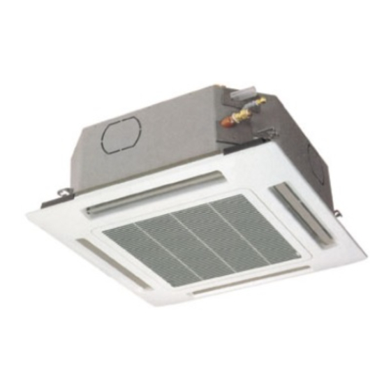
INDOOR UNIT:
CAF97R5IAA
CAF127R5IAA
CAF187R5IAA
SPLIT SYSTEM AIR CONDITIONER
Model No.
CAF97R5IAA
CAF127R5IAA
CAF187R5IAA
CAF98MR5IAA
CAF128MR5IAA
0.8180.533.1
CAF98MR5IAA
CAF128MR5IAA
Product Code No.
38.7106.005
38.7106.006
38.7106.007
38.7106.015
38.7106.016
06/2008
Advertisement
Table of Contents

Subscribe to Our Youtube Channel
Related Manuals for Technibel Climatisation CAF97R5IAA


Summary of Contents for Technibel Climatisation CAF97R5IAA
- Page 1 TECHNICAL DATA & SERVICE MANUAL CAF97R5IAA CAF98MR5IAA INDOOR UNIT: CAF127R5IAA CAF128MR5IAA CAF187R5IAA SPLIT SYSTEM AIR CONDITIONER Model No. Product Code No. CAF97R5IAA 38.7106.005 CAF127R5IAA 38.7106.006 CAF187R5IAA 38.7106.007 CAF98MR5IAA 38.7106.015 CAF128MR5IAA 38.7106.016 0.8180.533.1 06/2008...
- Page 2 IMPORTANT! • Ground the unit following local electrical codes. • The Yellow/Green wire cannot be used for any connection Please read before installation different from the ground connection. • Connect all wiring tightly. Loose wiring may cause overheating This air conditioning system meets strict safety and operating at connection points and a possible fire hazard.
-
Page 3: Table Of Contents
Table of Contents Page 1. SPECIFICATIONS 1-1 Unit specifications 1-2 Major Component specifications 1-3 Other Component specifications 2. DIMENSIONAL DATA 3. ELECTRICAL DATA 3-1 Electric Wiring Diagrams 4. FUNCTION 4-1 Operation Functions 11-12 4-2 Protective Functions 13-14 4-3 Drain Pump and Float Switch 5. -
Page 4: Specifications
1. SPECIFICATIONS 1-1 Unit Specifications CAF 97/127 R5IAA - CAF 98/128 MR5IAA 220 - 240 V ~ 50 Hz Power source 230 V Voltage rating Performance See catalogue with the requested matching Capacity High/Med./Low 700/600/500 Air circulation m³/h Features Microprocessor/ I.C. thermostat Controls/Temperature controls Control unit Wireless remote control unit... - Page 5 CAF 187 R5IAA 220 - 240 V ~ 50 Hz Power source 230 V Voltage rating Performance See catalogue with the requested matching Capacity High/Med./Low 790/660/580 Air circulation m³/h Features Controls/Temperature controls Microprocessor/ I.C. thermostat Wireless remote control unit Control unit ON/OFF 24 hours &...
-
Page 6: Major Component Specifications
1-2 Major Component Specifications CAF 97/127 R5IAA - CAF 98/128 MR5IAA Controller PCB Part No. CB-XRV93EH CAF97R5I CB-XRV123EH CAF127R5I CB-XMRV94EH CAF98MR5I CB-XMRV124EH CAF128MR5I Microprocessor Controls 250 V - 3,15 A Control circuit fuse RCS-4HVPN4EX Remote Control Unit CAF97/127R5I RCS-4MHVPNW4EX RCS-4MHVPN4EX CAF98/128MR5I Fan &... - Page 7 CAF 187 R5IAA Controller PCB Part No. CB-XRV184EH Microprocessor Controls Control circuit fuse 250 V - 3,15 A RCS-4MHVPNW4EX Remote Control Unit Fan & Fan Motor Centrifugal fan Type 1…. Ø 280 / L 166 Q'ty ……. Dia. and lenght Fan motor model…Q'ty K35407 M01972 …1 4…...
-
Page 8: Other Component Specifications
1-3 Other Component Specifications CAF 97/127 R5IAA CAF 98/128 MR5IAA CAF 187 R5IAA ATR-I55 Trasformer (TR) AC 230 V, 50/60 Hz Rating Primary 13.7 V - 0.4 A Secondary 5.48 VA Capacity Ω (at 25°C) Primary (WHT-WHT): 307 ± 10% Coil resistance Secondary (BRN-BRN): 1.8 ±... -
Page 9: Dimensional Data
2. DIMENSIONAL DATA Unit: mm REFRIGERANT TUBING JOINT WIDE TUBE: CAF97/127R5I - CAF98/128MR5I o.d. 9,52 (3/8) CAF187R5I o.d. 12,7 (1/2) -
Page 10: Electrical Data
3. ELECTRICAL DATA 3-1 Electric Wiring Diagrams CAF 97/127 R5IAA CAF 187 R5IAA CAF 98/128 MR5IAA... -
Page 11: Function
4. FUNCTIONS 4-1 Operation Functions... -
Page 13: Protective Functions
4-2 Protective Functions... -
Page 15: Drain Pump And Float Switch
4-3. Drain Pump and Float Switch... -
Page 16: Test Run
5. TEST RUN 5-1 How to Test Run the Air Conditioner display area HIGH POWER button ON/OFF 1HR. TIMER operation button button... -
Page 17: Troubleshooting
6. TROUBLESHOOTING 6-1 Precaution before Performing Inspection or Repair 6-2 Method of Self-Diagnostics ON/OFF button 1HR. TIMER button (reset) button... - Page 18 (1) Self-diagnostics lamps OPERATION lamp TIMER lamp SERVICE lamp + Since the indications cover various units, the corresponding parts listed below may not be present in some models. (2) If the self-diagnostics function fails to operate...
-
Page 19: Checking The Indoor And Outdoor Units
6-3 Checking the Indoor and Outdoor Units... -
Page 20: Noise Malfunction And Electromagnetic Interference
6-4 Noise Malfunction and Electromagnetic Interference... -
Page 21: Checking Electrical Components
7. CHECKING ELECTRICAL COMPONENTS 7-1 Measurement of insulation Resistance... -
Page 22: Checking Continuity Of Fuse On Pcb Assy
7-2 Checking Continuity of fuse on PCB Assy 7-3 Checking Motor Capacitor... - Page 23 R.D. 28 Reyrieux BP 131 - 01601 Trévoux CEDEX France Tél. 04.74.00.92.92 - Fax 04.74.00.42.00 R.C.S. Bourg-en-Bresse B 759 200 728...
Need help?
Do you have a question about the CAF97R5IAA and is the answer not in the manual?
Questions and answers