Table of Contents
Advertisement
Advertisement
Table of Contents
Troubleshooting

Subscribe to Our Youtube Channel
Related Manuals for TurboChef C3/AB


Summary of Contents for TurboChef C3/AB
- Page 1 C3/AB, C3/C, C3Multi, C3/CMulti CONVECTION MICROWAVE OVEN SERVICE AND REPAIR MANUAL TURBOCHEF TECHNOLOGIES INC. www.turbochef.com 10500 Metric Drive, Suite 128, Dallas, Texas 75243 USA (800) 908 TURBO (8-8726) © 2004 - TurboChef Technologies Inc PN: TC3-0215 Rev. D January 2, 2004...
- Page 2 TurboChef Technologies, Inc. This page intentionally left blank.
-
Page 3: Table Of Contents
Test Test Function Detailed Description ……………………………………………… 5-2 Passwords for Operating C3 ovens Chapter 6 Electrical Compartment & Controls Electrical Component Locations C3/AB Electrical Component Locations C3/C Electrical Component Locations C3/Multi Electrical Component Locations C3/C Multi Electrical Component Parts Lists Control Panel Detail... - Page 4 Door Removal and Replacement Right Side Parts List C3/C AND C3/CMULTI Door Assy and Parts List Chapter 7 Cook Door C3/AB and C3MULTI Door Assy and Parts List Chapter 8 Convection Circuit Catalytic Converter ………………………………………………………………. Convection Element and Thermocouples ………………………………………...
-
Page 5: Read This First
FAILURE TO DO SO MAY RESULT IN DEATH OR SERIOUS INJURY. PLEASE NOTE: THIS MANUAL ONLY COVERS C3/AB OVENS PRODUCED BY THE BLODGETT OVEN CORPORATION, C3MULTI OVENS PRODUCED TURBOCHEF, C3/C AND C3/CMULTI OVENS PRODUCED BY TURBOCHEF TECHNOLOGIES IN CHINA. -
Page 6: Important Safety Instructions
IMPORTANT SAFETY INSTRUCTIONS WHEN USING ELECTRICAL APPLIANCES, THE FOLLOWING BASIC SAFETY PRECAUTIONS SHOULD BE STRICTLY ADHERED TO: WARNING!! To reduce the risk of burns, electric shock, fire, injury to persons or exposure to excessive microwave energy: 1. Read all instructions before using the appliance. 2. -
Page 7: Precautions To Avoid Possible Exposure To Excessive Microwave Energy
PRECAUTIONS TO AVOID POSSIBLE EXPOSURE TO EXCESSIVE MICROWAVE ENERGY 1. DO NOT attempt to operate this oven with the door open since open-door operation can result in harmful exposure to microwave energy. It is important not to defeat or tamper with the safety interlocks. 2. -
Page 8: Precautions To Be Observed Before And During Servicing To Avoid Possible Exposure To Excessive Microwave Energy
PRECAUTIONS TO BE OBSERVED BEFORE SERVICING TO AVOID POSSIBLE EXPOSURE TO EXCESSIVE MICROWAVE ENERGY 1. DO NOT operate or allow the oven to be operated with the door open. 2. Make the following safety checks on all ovens to be serviced before activating the magnetron or other microwave source, and make repairs as necessary: a) Interlock operation. -
Page 9: Grounding Instructions
Metric component. Care has been given in this manual to list the different part numbers for the Metric and Imperial (C3/AB and C3Multi) ovens. In addition, please note that most hardware on the C3/C and C3/Cmulti oven is metric unless otherwise specified. -
Page 10: Rf Interference Considerations
RF INTERFERENCE CONSIDERATIONS This oven generates radio frequency signals. This device has been tested and determined to be in compliance with applicable part of FCC part 18 requirements and to the protection requirements of Council Directive 89/336/EEC on the approximation of the laws of the Member States relating to electromagnetic compatibility at the time of manufacture. -
Page 11: Installation Specs
CHAPTER 1 INSTALLATION SPECS... -
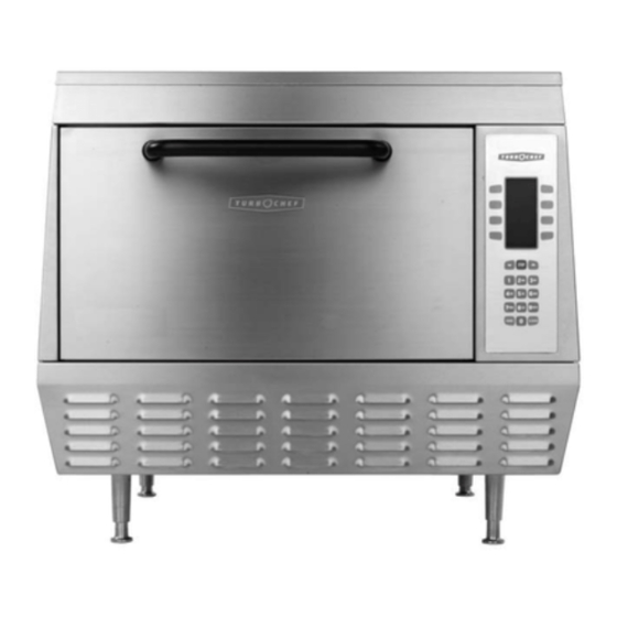
Page 12: Oven Description
C3/AB, C3MULTI, C3/C, AND C3/CMULTI 29” W x 25.5” H x 29.5” D (73.66 cm x 64.77 cm x 74.93 cm) 29” W x 43” H x 29.5” D (73.66 cm x 109.22 cm x 74.93 cm) 7.2 kW... -
Page 13: Oven Location
Installation Specs OVEN LOCATION The well planned and proper placement of your oven will result in long term operator convenience and satisfactory performance. Be sure to place the oven in an area which is accessible for proper operation and servicing. The countertop or work surface must be able to support weight... - Page 15 CHAPTER 2 CLEANING & OPERATING...
-
Page 16: Basic Cleaning Procedures
TurboChef Technologies, Inc. C Series BASIC CLEANING PROCEDURES PROBLEMS ASSOCIATED WITH IMPROPER CLEANING The oven may not be operating correctly because it is not being cleaned properly. If the door is leaking microwaves, erratic operation of the display and other electrical components can occur. -
Page 17: Theory Of Operation
CHAPTER 3 THEORY OF OPERATION... - Page 18 TurboChef Technologies, Inc. C Series INTRODUCTION The TurboChef C3/C oven utilizes two independent heat transfer mechanisms in order to rapidly cook food. The systems are as follows: Convection and Microwave energy. By combining these mechanisms and with our ability to control each mechanism independently, we are able to reduce the cook time of most foods by 70%-90%.
-
Page 19: Theory Of Operation Description
GLOSSARY OF COMMON OPERATING TERMS Display - Primary interface to relay messages to the operator. Keypad - Primary interface for the operator to control the oven. Cook Chamber - Cavity in which the food products are cooked. PRODUCT RECIPES Recipe - The food product recipe programming consists of total time, percent total... - Page 20 TurboChef Technologies, Inc. C Series Programing Edit Mode Edit mode enables the operator to alter Recipes and the Cook Chamber Temperature (CC). To Access Edit Mode, press the “Up” and “Down” Arrows Keys on the keypad simultaneously. When prompted, enter the Access Code “9” and then press “Enter”.
- Page 21 Figure 3-3: Edit Groups Use the “Up” and “Down” keys to navigate through a Recipe and use the Keypad and the “Enter” key to alter any of the following parameters: COOK TIME: Total duration of the Cook Cycle. Enter the desired time and press “Enter”.
- Page 22 TurboChef Technologies, Inc. C Series Figure 3-5: Time State To disable the Time State, press the “Back Arrow” and “Enter” keys simultaneously and “Enter” the Access Pin “T-I-M-E” and “Enter”. When prompted, press “9” to re- enable or any other key to disable the Time State.
-
Page 23: Fault Codes
CHAPTER 4 FAULT CODES... -
Page 24: Fault Code Introduction
14ºF (~8ºC) F in 30 seconds. Reference Chpt. 8 NOTE: Some error codes may be different or no longer available or current. The following list details all error codes created since C3/AB, C3/C, C3CMulti and C3/AB-Multi no exceptions. C) differential of the compartment... - Page 25 Fault Code Messages Matrix New Error Old Error Code BLOWER STATUS F3 BLOWER LOW COOK TMP F2 LOW TEMP LOW MAG CURR F3 MAG CURR DOOR MONITOR F4 MONITOR MAG OVER TMP F5 MAG TEMP ELEC OVR TMP F6 EC TEMP HX RISE LOW THERMO OPEN OVEN DOOR AJAR...
-
Page 27: Chapter 5 Test
CHAPTER 5 TEST... - Page 28 TurboChef Technologies, Inc. C Series Test Mode TO ENTER TEST FUNCTION MODE 1. From the standby mode, press and hold both BACK simultaneously. 2. The display reads: ENTER ACCESS CODE 3. Use the NUMERIC keypad to enter the following access code: 9- 4- 2- 8 (Older Ovens 8- 3 -1 -7) 4.
- Page 29 ELEC OVR TMP (electronics compartment over temperature detection) DOOR MONITOR: (cook door monitor switch out of sequence)* * NOTE: The C3/C model and late model C3/AB oven will have the LOW MAG FLUC error message replaced by the DOOR MONITOR error message. Idle Airflow The first press of the IAF key displays the selected idle airflow.
- Page 30 TurboChef Technologies, Inc. C Series...
-
Page 32: Passwords For Operating C3 Ovens
TurboChef Technologies, Inc. C Series PASSWORDS FOR OPERATING C3/C OVENS with C3AD Software Version To access TEST/SERVICE functions, press and hold BACK and ENTER keys. At the “Enter Pin ____” prompt, key in 9428 (Older ovens 8317) “WHAT” and press Enter. Reference Chapter 5 To access recipe EDIT, press and hold Up and Down arrow keys. - Page 33 CHAPTER 6 ELECTRICAL &CONTROLS SYSTEM...
-
Page 34: Electrical Component Locations C3/C Multi
6c K3 RELAY& SOCKET 6d K6 RELAY& SOCKET 7 K5 SOLID STATE RELAY FOR HEATER 8 K4 SOLID STATE RELAY FOR MAGNETRON (101285) 9 SMT CONTROLLER BOARD FIGURE 6–1a Electrical Component Locations C3/AB Only (T0322) 10. COOLING FAN (100596) 11. MAGNETRON COOLING FAN (100597) 12. - Page 35 Electrical Component Locations: 1. Circuit Breaker: CB1-35Amp with trip coil 2. Fuses: (2x12 AMP-C3/AB & C3/C) (25AMP-C3/C) 3. Convection Heat High Limit 4 24VDC POWER SUPPLY 6a K1 RELAY& SOCKET (T0278 &T0309) 6b K2 RELAY& SOCKET (T0278 &T0309) 6c K3 RELAY& SOCKET (T0278 &T0309)
- Page 36 TurboChef Technologies, Inc. C Series ELECTRICAL COMPONENT LOCATIONS: “C3/MULTI” OVENS ONLY 1. Circuit Breaker: CB1-15A & CB2-15A&CB3-15A (103170) 2. 12 A-FUSE ATM-12 3. CONVECTION HEAT HIGH LIMIT 4. 24VDC POWER SUPPLY 5. DISTRIBUTION BLOCK 6a. K2 RELAY& SOCKET 6b. K3 RELAY& SOCKET 6c.
- Page 37 ELECTRICAL COMPONENT LOCATIONS: “C3/C MULTI” OVENS ONLY 1. Circuit Breaker: CB1-15A & CB2-15A&CB3-15A (103170) 2. 12 A-FUSE ATM-12 3. CONVECTION HIGH LIMIT 4. 24VDC POWER SUPPLY 5. DISTRIBUTION BLOCK 6a. K1 RELAY& SOCKET (T0278 &T0309) 6b. K2 RELAY& SOCKET (T0278 &T0309) 6c.
-
Page 38: Electrical Component Parts Lists
Magnetron Cooling Fan Stirrer Motor HV Diode HV, Capacitor, 2500 V Filament Transformer Magnetron Transformer T1 Magnetron Blower Motor Speed Controller Used on Model(s) C3/AB & C3/C C3/C C3/AB & C3/C C3Multi & C3/CMulti C3/AB & C3Multi C3/C & C3/CMulti... - Page 39 Convection Motor Assy Circuit Breakers CB2 & CB3 15 Amp K7 Solid State Relay Thermostat, Magnetron (212F) Thermostat, EC Box EMI Filters (not shown) EMI Filter Used on Model(s) C3Multi & C3/CMulti C3Multi & C3/CMulti C3Multi & C3/CMulti C3/AB & C3/C...
-
Page 40: Control Panel Detail
TurboChef Technologies, Inc. C Series CONTROL PANEL COMPONENT DETAIL CONTROL PANEL PARTS LIST (see above) ITEM Part Description Used on Model(s) Number... -
Page 41: Control System Troubleshooting
CONTROL SYSTEM TROUBLESHOOTING Issue: Resolutions: 1: No Display (Blank) 2. No Keypad Input 1. Check operation of rear cooling fan. Reference Schematic in Chapter a. ELEC OVR TMP; “or” b. EC TEMP HIGH; “or” c. F6 EC TEMP Electrical Compartment and Controls Verify power 208 VAC or 240 VAC is going to oven. - Page 42 TurboChef Technologies, Inc. C Series Defective Current Transformer on Computer Board SMT Board (T0265) Background: During the operation of the microwave system, the control board monitors current in the microwave circuit by means of a current transformer mounted on the controller board. The current transformer must see at least 6 amps in order for the microwave to energize.
- Page 43 CHAPTER 7 COOK DOOR ASSEMBLY...
- Page 44 DOOR SWITCHES AND CIRCUIT BREAKERDOOR SWITCHES The C series ovens have 3 door switches as mandated by law. The C3/AB and C3Multi have one door switch located on the left hand side (CDS) and is called the secondary switch. The other two switches are located on the right hand side (CDP &...
-
Page 45: Chapter 7 Cook Door
High limit & K1 relay High limit tripped (670 F/350 C). Reset high limit switch with screwdriver. Reference Page 8-4 for details (C3/AB and C3/C only) Door switch closure Check Switches with VOM meter. Reference Page 7-2 & Figure 7-1 above. -
Page 46: Door Switch Adjustment
(secured by one PPH screw at rear of oven). The plenum assembly is located on the bottom right side of the oven. 6. On models C3/AB and C3Multi it may be necessary to remove the 35 AMP circuit breaker in order to gain access to the limit switches. - Page 47 13. Actuator tab should be positioned as shown in Figure 7-5. It should be parallel to the primary switch lever. (needle nose pliers) actuator tab as necessary. 14. When the door is closed and the actuator tab is in contact with the primary and monitor switches the switches should both be closed.
- Page 48 TurboChef Technologies, Inc. C Series Figure 7-3 Interlock Placement Differences C3/AB vs. C3/C...
- Page 49 Cook Door Figure 7-4 Trailing Arm and Cam Motion...
- Page 51 Cook Door Figure 7-58: Interlock Switch Adjustment...
-
Page 52: Door Removal And Replacement
TurboChef Technologies, Inc. C Series DOOR REMOVAL AND REPLACEMENT Tools Required: 12” long #2 Phillips screw driver 3/8” hex driver 3/8” socket with 1/4” ratchet wrench Set of feeler gages Large flat blade screw driver DOOR REMOVAL 1) Remove the side and top panels, top and bottom molding, control panel, and left perimeter trim piece. -
Page 53: Chapter 7 Cook Door
By design there is a 0.030” clearance between Phillips securing the plastic shunt cover and the oven flange on the C3/AB and C3Multi. The C3/C and C3/CMulti gap should be 0.060” (1.50 mm). more of these screws does not contact... - Page 54 TurboChef Technologies, Inc. C Series FIGURE 7 – 6a C3/C & C3/Cmulti (Left Side) 7-12...
- Page 55 Cook Door DOOR REMOVAL AND REPLACEMENT PARTS LIST (LEFT SIDE): See Figure 4-3 & 4-7a. ITEM Part Description Used on Model(s) Number 7-13...
- Page 56 TurboChef Technologies, Inc. C Series DOOR REMOVAL AND REPLACEMENT PARTS LIST (LEFT SIDE) CON’T See Figure 4-7a. ITEM Part Description Used on Model(s) Number 7-15...
- Page 57 Cook Door FIGURE 7 – 6b Door Removal and Replacement (Right Side) 7-16...
- Page 58 TurboChef Technologies, Inc. C Series DOOR REMOVAL AND REPLACEMENT PARTS LIST (RIGHT SIDE): See Figure 4-7b ITEM Part Description Used on Model(s) Number 7-17...
- Page 59 Cook Door Figure 7-8: C3/C and C3/CMulti Door Assembly 7-18...
- Page 60 TurboChef Technologies, Inc. C Series C3/C AND C3/CMULTI DOOR ASSEMBLY PARTS: See Figure 4-8 Item Part Description Used on Model(s) Number 7-19...
- Page 61 Cook Door C3/C AND C3/CMULTI DOOR ASSEMBLY PARTS (CON’T): See Figure 4-8 Item Part Description Used on Model(s) Number 7-20...
- Page 62 TurboChef Technologies, Inc. C Series Figure 7-9: C3/AB and C3Multi Door Assembly 7-21...
- Page 63 Cook Door C3/AB AND C3MULTI DOOR ASSEMBLY PARTS: See Figure 4-9 Item Part Description Used on Model(s) Number 7-22...
-
Page 64: Convection Circuit
CHAPTER 8 CONVECTION CIRCUIT... -
Page 66: Catalytic Converter
(Note: The Return Air Duct Assembly Panel and the Terminal Heat Shield may be inverted on some C3/AB units. All C3/C units will have this assembly inverted). It is important to carefully remove the insulation and replace it neatly. -
Page 67: Convection Element And Thermocouples
H to the un-highlighted position (this indicates the heater circuit is energized). On the C3/AB and C3/C, only, one of the heater wires to the hot air element is looped through an inductance coil transformer on the I/O control circuit assembly. -
Page 68: Heater Circuit Defective Messages
TurboChef Technologies, Inc. C Series Heater Circuit Defective Messages SELF TEST (STEST) WHILE COOKING (WARMING UP) THERMO OPEN THERMO OPEN HX RISE LOW HX RISE LOW LOW COOK TMP (F3 LOW TEMP) CAUSE HX Thermocouple amplifier 1. Check Thermocouple connections on I/O board connector (See I/O board indicates open, (999 )."or"... - Page 69 Convection Circuit FIGURE 8 - 1 Catalytic Converter Access Hi-Limit Thermostat (18) (HX)Thermocouple (17) FIGURE 8 - 2 Thermocouple & Thermostat Locations 8 - 5...
- Page 70 TurboChef Technologies, Inc. C Series CONVECTION ELEMENT ASSEMBLIES FIGURE 8-3 Convection Heater Assemblies OBSOLETE MODEL Note: TC3-0200 Kit Retrofit, Sheated Heater replaces the above obsolete model.
- Page 71 SCREW, #8-32 PPHD, CRES SCREW, M4 X 10 mm CATALYTIC CONVERTER TYPE K THERMOCOUPLE HI-LIMIT THERMOSTAT 8-10 Convection Circuit Used on Model(s) All (240 VAC) All (208 VAC) All (200 VAC) C3/AB, C3/C C3/AB, C3/C C3/AB, C3/C C3/AB C3/C C3/AB C3/C C3/AB, C3/C...
-
Page 73: Convection (Blower) Motor Operation
CONVECTION (BLOWER) MOTOR OPERATION The convection (blower) motor is a variable speed convection motor, which operates from zero rpm up to 7000 rpm. The blower motor speed is controlled by a SP200 AC/Delta drive control. The speed of the motor is directly proportional to the applied low voltage to the SP200 AC./Delta drive control from the control circuit card. -
Page 74: Blower Circuit Defective Messages
TurboChef Technologies, Inc. C Series Blower Circuit Defective Messages SELF TEST WHILE COOKING BLOWER STATUS BLOWER STATUS or "F1 BLOWER" or "F1BLOWER" CAUSE 1) Verify jumper on P3 of control Blower motor speed controller not returning the "running status command" See status indicator A Note: If the door is opening Pins 1&2=Reliance Controller... -
Page 75: Blower Motor Controller Fault Codes & Troubleshooting
Blower Motor Controller Fault Codes & Troubleshooting NOTE: If no fault condition exists, the LED will be green. If a fault condition exists, the LED will flash redhen a local keypad is not connected. All faults can be reset by cycling the reset control input, pressing the stop key, or cycling power, except as noted in the Corrective Action column below. - Page 76 TurboChef Technologies, Inc. C Series # of Fault Flashes Description Negative Slope Ground Short Phase to Phase Short Checksum Failure Microprocessor Fault TABLE 5 - 2 Reliance Blower Motor Controller Fault Codes & Troubleshooting Fault Cause Conflicting parameter values Phase U Phase V Phase W Phase U-V...
-
Page 77: Delta Blower Motor Controller Fault Codes & Trobleshooting
Delta Blower Motor Controller Fault Codes & Troubleshooting Fault Name Fault Descriptions The AC drive detects an abnormal increase in current. The AC drive detects that the DC bus voltage has exceeded its maximum allowable value. The AC drive temperature sensor detects excessive heat. - Page 78 TurboChef Technologies, Inc. C Series Delta Blower Motor Controller Fault Codes & Troubleshooting Fault Name Fault Descriptions Over-current during acceleration: 1. Short-circuit at motor output. 2. Torque boost too high. 3. Acceleration time too short. 4. AC drive output capacity is too small. Over-current during deceleration: 1.
- Page 79 Convection Circuit Figure 8-6: Convection Motor Detail PN: C0299 8-10...
-
Page 80: Convection Motor Parts List
TurboChef Technologies, Inc. C Series CONVECTION MOTOR PARTS LIST: See Figure 5-6 Item Part Description Used on Model(s) Number Special Kits & Assemblies Blower Hub Kit P/N: TC3-0238 consists of the following part numbers: 1- HUB, FAN SMALL: 700-0306-2 4- INTERNAL TOOTH WASHER: 101746 2- SET SCREW: 101715 4- BUTTON HEAD SCREWS: 102320 Notes:... - Page 81 This page intentionally left blank.
-
Page 83: Microwave Circuit
CHAPTER 9 MICROWAVE CIRCUIT... -
Page 84: Measuring For Microwave Radiation Leakage
TurboChef Technologies, Inc. C Series MEASURING FOR MICROWAVE RADIATION LEAKAGE The following RF emissions test must be performed every time a service call is done on a C3 SERIES oven. Report your findings on the work order. The following areas must be measured when performing the RF test. -
Page 85: Microwave Circuit Defective Messages
Microwave Circuit Defective Messages SELF TEST WHILE COOKING LOW MAG CURR LOW MAG CURR *HV BREAKDOWN *HV BREAKDOWN F3 MAG CURR F3 MAG CURR * European ovens only Note: If this message is detected while cooking it will terminate cook cycle immediately. - Page 86 TurboChef Technologies, Inc. C Series...
- Page 87 MAGNETRON CIRCUIT Overview of a microwave circuit The microwave circuit consists of a magnetron and a voltage doubler circuit. The voltage doubler consists of a special step–up transformer, a capacitor, a diode. In addition to the power circuitry in the magnetron the oven utilizes a filament transformer to pre-heat the magnetron filament before applying the high voltage to the anode.
-
Page 88: Magnetron High Voltage Power Supply
Magnetron High Voltage Transformer (102093) The magnetron transformer is a ferro-resonant design which limits fault currents and minimizes HV TRANSFORMER OUTPUT VOLTAGE +(B) +2400 V 2400 2400 Current Flow CAPACITOR CHARGES ON POSITIVE VOLTAGE SWING 1. The Magnetron Transformer steps up the input voltage to approximately 2400 volts peak (4800 volts peak to peak). - Page 90 TurboChef Technologies, Inc. C Series Filament Transformer(102091) Background: The filament transformer is a step down transformer from 208-240VAC to about 4-5VAC. This voltage pre-heats the magnetron filament allowing it to be ready once the magnetron is energized by the high voltage transformer. This method in the industry is known as hot start and highly used to increase the life expectancy of the magnetron.
-
Page 91: Magnetron Testing
MAGNETRON TESTING WARNING!! The microwave circuit cannot be worked on with the unit on. The unit must be disconnected from the power source. Failure to do so could result in injury or death. WARNING!! The HV Capacitor must be discharged before proceeding. -
Page 93: Component Testing (Diode, Capacitor, Transformer)
COMPONENT TESTING WARNING!! The microwave circuit cannot be serviced with the unit on. The unit must be disconnected from the power source. Failure to do so could result in injury or death. WARNING!! The HV Capacitor must be discharged before proceeding. WARNING!! Do not attempt to measure the magnetron anode or filament voltages. - Page 94 TurboChef Technologies, Inc. C Series WARNING!! Use extreme caution when taking any current readings. Failure to do so can result in death or serious injury. FILAMENT TRANSFORMER REAR VIEW (1-3) 240 VAC 27.8 OHMS (1-2) 200-208 VAC 23.2 OHMS FRONT VIEW T2 FILAMENT TRANSFORMER 240 VAC 200-208 VAC...
- Page 96 TurboChef Technologies, Inc. C Series Waveguide Components: Figure 9-6: Waveguide Assy 9-11...
- Page 97 Microwave Circuit WAVEGUIDE COMPONENTS PARTS LIST: See Figure 9-6 Item Part Description Used on Model(s) Number 9-12...
-
Page 98: Waveguide Components Parts List
TurboChef Technologies, Inc. C Series WAVEGUIDE COMPONENTS PARTS LIST (con’t): See Figure 9-6 Item Part Description Used on Model(s) Number 9-13... -
Page 99: (Smt)I/O Board & Schematics
CHAPTER 10 I/O Board & Schematics... - Page 100 TurboChef Technologies, Inc. C Series 10-2...
- Page 101 10-5...
- Page 102 TurboChef Technologies, Inc. C Series 10-4...
- Page 103 K4(MAGA) (8130F -44-93) 820MW4 K1(MAG FAN) 10-5...
- Page 104 TurboChef Technologies, Inc. C Series 1- Software EPROM 2- R51 Beeper Volume Adjustment 3- Microprocessor 4- P3- Blower Motor Controller Mode Selector SP200=1&2 5- R24- RF Fluctuation Adjustment (Optional) 6- R42- 5 Volt Reference Adjustment 7- P1 +5VDC Reference Point 10-6...
- Page 105 8- J2 40 Pin Connector (Most signal wires are terminated here!) 9- J5 26 Pin Flat Cable (from front panel VFD) 10- J3 5 VDC Power Supply to Vacuum Fluorescent Display 11- J1 RF Cable Connection (Optional) 12- J6 RS232 Cable (Menu Download port) 13- J4 Keypad membrane cable 14- Interlock Relays (Primary and Secondary) 10-7...
Need help?
Do you have a question about the C3/AB and is the answer not in the manual?
Questions and answers