
Related Manuals for Troy-Bilt Automatic Lawn Tractor


Summary of Contents for Troy-Bilt Automatic Lawn Tractor
- Page 1 Operator’s Manual IMPORTANT: READ SAFETY RULES AND INSTRUCTIONS CAREFULLY P. O. BOX 1386, KITCHENER, ONTARIO, CANADA N2G 4J1 PRINTED IN U.S.A. Automatic Lawn Tractor 772C0738 (12/2004)
-
Page 2: Finding Model Number
Content Customer Support Important Safe Operation Practices Slope Gauge Setting Up Know Your Lawn Tractor Operating Your Lawn Mower Adjustments This Operator’s Manual is an important part of your new lawn tractor. It will help you assemble, prepare and maintain the unit for best performance. -
Page 3: Section 1: Important Safe Operation Practices
SECTION 1: IMPORTANT SAFE OPERATION PRACTICES WARNING: This symbol points out important safety instructions which, if not followed, could endanger the personal safety and/or property of yourself and others. Read and follow all instructions in this manual before attempting to operate this machine. Failure to comply with these instructions may result in personal injury. -
Page 4: Slope Operation
25. Disengage all attachment clutches, depress the brake pedal completely and shift into neutral before attempting to start engine. 26. Your machine is designed to cut normal residential grass of a height no more than 10”. Do not attempt to mow through unusually tall, dry grass (e.g., pasture) or piles of dry leaves. -
Page 5: Safe Handling Of Gasoline
To avoid back-over accidents, always disengage the cutting blade(s) before shifting into reverse. The “Reverse Caution Mode” should not be used when children or others are around. g. Keep children away from hot or running engines. They can suffer burns from a hot muffler. - Page 6 9. After striking a foreign object, stop the engine, disconnect the spark plug wire(s) and ground against the engine. Thoroughly inspect the machine for any damage. Repair the damage before starting and operating. 10. Never attempt to make adjustments or repairs to the machine while the engine is running.
-
Page 7: Section 2: Slope Gauge
SECTION 2: SLOPE GAUGE Use this page as a guide to determine slopes where you may not operate safely. Do not operate your lawn tractor on such slopes. -
Page 8: Section 3: Tractor Set-Up
SECTION 3: TRACTOR SET-UP NOTE: This owner’s manual covers various models of lawn tractors. The units illustrated may vary slightly from your unit. Follow only those instructions which pertain to your model lawn tractor. Attaching the Battery Cables NOTE: The positive battery terminal is marked Pos. (+). -
Page 9: Attaching The Steering Wheel
WARNING: The mowing deck is capable of throwing objects. Failure to operate the riding mower without the discharge cover in the proper operating position could result in serious personal injury and/or property damage. Attaching the Steering Wheel WARNING: Do NOT operate the tractor without first attaching both the steering wheel AND the seat. -
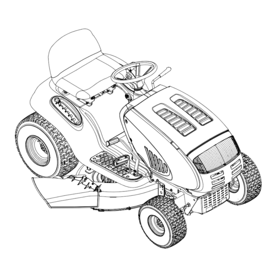
Page 10: Section 4: Know Your Lawn Tractor
KNOB ADJUSTMENT Knobs Shoulder Screws Opening in Slot Pivot Bracket Figure 5 SECTION 4: KNOW YOUR LAWN TRACTOR Throttle Control Lever The throttle control lever is located on the right side of the tractor’s dash panel. This lever controls the speed of the engine and, on some models, when pushed all the way forward, the choke control also. - Page 11 † † Systems Indicator Monitor/Hour Meter PTO (Blade Engage) Lever PTO (Blade Engage) Knob Choke Knob Parking Brake Button Shift Lever Cup Holder NOTE: Any reference in this manual to the RIGHT or LEFT side of the tractor is observed from operator’s position. NOTE: Hood styles vary by model.
-
Page 12: Ignition Switch Module
Ignition Switch Module WARNING: Never leave a running machine unattended. Always disengage PTO, move shift lever into neutral position, set parking brake, stop engine and remove key to prevent unintended starting. To start the engine, insert the key into the ignition switch and turn clockwise to the START position. -
Page 13: Seat Adjustment Lever
Electric PTO (Blade Engage) Knob To engage the power to the cutting deck or other (separately available) attachments on models equipped with an electric PTO, pull outward on the PTO (Blade Engage) knob. Push the PTO (Blade Engage) knob inward to disengage the power to the cutting deck. NOTE: The PTO (Blade Engage) knob must be in the disengaged (OFF) position when starting the engine,... -
Page 14: Shift Lever
Shift Lever The shift lever is located on the left side of the fender and has three positions, FORWARD, NEUTRAL and REVERSE. The brake pedal must be depressed and the tractor must not be in motion when the moving shift lever. -
Page 15: Setting The Cutting Height
3. Depress the REVERSE PUSH BUTTON (Orange, Triangular Button) at the top, right corner of the key switch module. The red indicator light at the top, left corner of the key switch module will be ON while activated. See Figure 11. 4. -
Page 16: Stopping The Engine
Stopping the Engine WARNING: If you strike a foreign object, stop the engine, disconnect the spark plug wire(s) and ground against the engine. Thoroughly inspect the machine for any damage. Repair the damage before restarting and operating • If the blades are engaged, place the PTO (Blade Engage) knob (or lever) in the disengaged (OFF) position. - Page 17 Models with Manual PTO • Grasp the PTO (Blade Engage) lever and pivot it all the way forward into the engaged (ON) position. Models with Electric PTO • Pull the PTO (Blade Engage) knob outward into the engaged (ON) position. See Figure 12. Front View Pull Out Figure 12...
-
Page 18: Leveling Deck
SECTION 6: MAKING ADJUSTMENTS WARNING: Never attempt to make any adjustments while the engine is running, except where specified in the operator’s manual. Leveling the Deck NOTE: Check the tractor’s tire pressure before performing any deck leveling adjustments. Refer to Tires section for information regarding tire pressure. -
Page 19: Steering Adjustment
If the tractor does not come to a complete stop when the brake pedal is completely depressed, or if the tractor’s rear wheels can roll with the parking brake applied, the brake is in need of adjustment. The brake disc can be found on the right side of the transmission in the rear of the tractor. -
Page 20: Section 7: Maintaining Your Lawn Tractor
SECTION 7: MAINTAINING YOUR LAWN TRACTOR WARNING: Before maintenance or repairs, disengage PTO, move shift lever into neutral position, set parking brake, stop engine and remove key to prevent unintended starting. Engine Refer to the separate engine manual for engine maintenance instructions. -
Page 21: Section 8: Service
Deck Wash System™ (Optional) A hex plug can be found on your tractor’s deck surface. This plug can be replaced with a water port to be used as part of a separately-available deck wash system. Use the Deck Wash System to rinse grass clippings from the deck’s underside and prevent build-up of corrosive chemicals. -
Page 22: Cutting Blades
• Always keep the battery cables and terminals clean and free of corrosive build-up. • After cleaning the battery and terminals, apply a light coat of petroleum jelly or grease to both terminals. • Always keep the rubber boot positioned over the positive terminal to prevent shorting. - Page 23 If the cutting edge of the blade has already IMPORTANT: been sharpened to within 5/8" of the wind wing radius, or if any metal separation is present, replace the blades with new ones. See Figure 20. Worn Blade Edge Wind Wing Sharpen Edge Evenly Figure 20 It is important that each cutting blade edge be ground...
-
Page 24: Changing The Transmission Drive Belts
46-inch Decks with Electric PTO Insert a 3/8”-drive ratchet wrench (set to loosen) into the square hole found in the idler bracket on the left side of the deck’s surface. See Figure 22. • Grasp the ratchet’s handle and pivot it toward the tractor’s right side to relieve tension on the belt. -
Page 25: Section 9: Off-Season Storage
Idler Bracket Figure 22 SECTION 9: OFF-SEASON STORAGE Clean and lubricate the tractor as instructed in MAINTAINING YOUR LAWN TRACTOR of this manual before storing for an extended period. WARNING: Drain fuel only into an approved container outdoors, away from an open flame. -
Page 26: Section 11: Troubleshooting
SECTION 11: TROUBLESHOOTING Trouble Possible Cause(s) Engine fails to start PTO engaged. Parking brake not engaged. Spark plug wire(s) disconnected. Throttle control lever not in correct starting position. Choke not activated Fuel tank empty, or stale fuel. Blocked fuel line. Faulty spark plug. - Page 27 For TWO YEARS from the date of retail purchase within Canada, MTD PRODUCTS LIMITED will, at its option, re - pair or replace, for the original purchaser, free of charge, any part or parts found to be defective in material or workmanship.
Need help?
Do you have a question about the Automatic Lawn Tractor and is the answer not in the manual?
Questions and answers