Table of Contents
Advertisement
Available languages
Available languages
Quick Links
www.aeropurefans.com
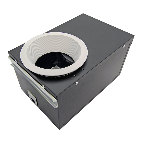
MODEL: AP80-RVL
AP80H- RV L
AP100-RVL
WARNING
TO REDUCE THE RISK OF FIRE, ELECTRIC SHOCK, OR INJURY TO PERSONS, PLEASE READ THE FOLLOWING:
1. Use this unit only in the manner intended by the manufacturer. If you have questions, contact the manufacturer at the address or telephone number
listed in the warranty. 2.Before servicing or cleaning unit, switch power off at service panel and lock the service disconnecting means to prevent power
from being switching on accidentally. If the service disconnecting means cannot be locked, securely fasten a prominent warning device, such as a tag,
to the service panel. 3. Installation work and electrical wiring must be done by a licensed person(s) in accordance with all applicable codes and
standards, including fire-rated construction codes and standards. 4. Sufficient air is needed for proper combustion and exhausting of gases through
the flue (chimney) of fuel burning equipment to prevent backdraft. Follow the heating equipment manufacturer's guideline and safety standards such
as those published by the National Fire Protection Association (NFPA), and the American Society for Heating, Refrigeration and Air Conditioning
Engineers (ASHRAE), and the local code authorities. 5. When cutting or drilling into wall or ceiling, do not damage electrical wiring and other hidden
utilities. 6. Ducted fans must always be vented to the outdoors. 7. Acceptable for use over a tub or shower when connected to a GFCI (Ground Fault
Circuit Interrupter) - protected branch circuit. 8. This unit must be grounded. 9. Never place a switch where it can be reached from a tub or shower.
10. WARNING: To reduce the risk of fire or electric shock, do not use this fan with any solid-state speed control device. 11. The fan must not be
installed in a ceiling thermally insulated to a value greater than R40.
CAUTION
1. For general ventilating use only. Do not use to exhaust hazardous or explosive materials and vapors.
2. This product is designed for installation in ceilings up to a 12/12 pitch (45 degree angle). Duct connector must be horizontal. DO NOT
MOUNT THIS PRODUCT IN A WALL.
3. To avoid motor bearing damage and noisy and/or unbalanced impellers, keep drywall spray, construction dust, etc. off power unit.
4. Please read specification label on product for further information and requirements.
CLEANING & MAINTENANCE
For quiet and efficient operation, long life, and attractive appearance lower or remove grille and vacuum interior of unit with the dusting brush
attachment.
The motor is permanently lubricated and never needs oiling.
OPERATION
Use an on/off switch to operate this fan. See "Connect Wiring" for details.
The humidity control and fan can be operated separately. Can be used with a dual "stacked" switch for fan / light control. Do not use a dimmer switch
to operate the humidity control or light. See "Connect Wiring" for details.
For AP80H-RVL & AP80H-QVL & AP100H-RVL
SENSOR OPERATION
The humidity-sensing fan uses a sophisticated humidity sensor that responds to: (a) rapid to moderate (user-adjustable) increases in humidity or (b)
humidity rate above a user-adjustable set-point (30%-80% relative humidity). The humidity sensor may occasionally turn the fan ON when
environmental conditions change. If the fan continuously responds to changing environmental conditions, adjustment may be required. The fan is
factory-set for 80% (with a ambient temperature of 77 degree F)
SENSITIVITY ADJUSTMENT (H)
The "H" has been factory set for most shower applications. However, if the fan is in a tub area or is being used for dampness control, the "H"
may need to be increased toward maximum "+". If the control is responding too often to changing environmental conditions, movement toward less "-"
"H" may be required. To adjust the "H":
1. Disconnect power at service entrance.
2. Through the grille, locate the slot marked "H".
3. Carefully rotate the "H" adjustment toward "+" or "-".
4. Turn on power and check operation by turning on the shower or other humidity source until the fan turns on.
5. Repeat above steps if necessary.
When the ambient temperature changes, the humidity sensor values will deviate slightly.
TIMER ADJUSTMENT (T)
The "T" on the control panel will adjust the time delay from 5 to 60 minutes (factory pre-set at 20 minutes). This "T" controls the length of time that the
fan remains ON after the sensor has stopped sensing a rise in humidity and the humidity level is below the user-adjustable set-point. To adjust the "T":
1. Disconnect power at service entrance;
2. Through the grille, locate the slot marked "T";
3. Carefully rotate the "T" adjustment to desired setting (from 5 to 60 minutes).
4. Check operation by turning on a humidity source until the fan turns on.
5. Turn humidity source off and time the unit.
6. Repeat above steps if necessary.
Installer: Leave this manual with the homeowner.
AP80-QVL
AP80H- QVL
AP100H-RVL
READ AND SAVE THESE INSTRUCTIONS
RECESSED FAN LIGHT
Cod:0060300920-E
Advertisement
Table of Contents

Related Manuals for aero pure AP80H-RVL


Summary of Contents for aero pure AP80H-RVL
- Page 1 The humidity control and fan can be operated separately. Can be used with a dual “stacked” switch for fan / light control. Do not use a dimmer switch to operate the humidity control or light. See “Connect Wiring” for details. For AP80H-RVL & AP80H-QVL & AP100H-RVL SENSOR OPERATION The humidity-sensing fan uses a sophisticated humidity sensor that responds to: (a) rapid to moderate (user-adjustable) increases in humidity or (b) humidity rate above a user-adjustable set-point (30%-80% relative humidity).
-
Page 2: Plan The Installation
PLAN THE INSTALLATION 1. Do not use in a cooking area. 2. Two ways to connect ductwork to a factory-shipped unit. INSULATION* ROOF CAP* (Place around and (with built-in over Fan Housing.) damper) POWER HOUSING CABLE* Keep duct runs short Seal gaps around Housing. -
Page 3: Connect Electrical Wiring
AP80-RVL AP100-RVL AP80-QVL BLACK(BLK) WHITE(WHT) BLUE(BLU) GROUND (GRD) UNIT LIGHT WIRE PANEL SWITCH BOX LIGHT RECEPTACLE RECEPTACLE POWER SUPPLY 120V AC AP80H-RVL AP80H-QVL AP100H-RVL BLACK (BLK) WHITE (WHT) BLUE(BLU) BROWN (BRN) SWITCH GROUND (GRD) W HT UNIT SENSOR WIRE PANEL HUMIDITY... -
Page 4: Service Parts
Wire Panel SERVICE PARTS PART PART NAME Qty. Trim Ring ( AP80-RVL & AP80H-RVL & AP100-RVL & AP100-RVL) Trim Ring ( AP80-QVL & AP80H-QVL) Grille Spring Lamp base Humidity Sensor System (AP80H-QVL&AP80H-RVL) Wire Panel / Harness Assembly... - Page 5 www.aeropurefans.com AP80-RVL AP80-QVL AP80H- RV L AP80H- QVL AP100-RVL AP100H-RVL...
- Page 7 AP80-RVL AP100-RVL AP80-QVL AP80H-RVL AP80H-QVL AP100H-RVL SWITCH BRUN(BRN) W HT DU DÉTECTEUR D'HUMIDITÉ DU DÉTECTEUR D'HUMIDITÉ SENSOR SWITCH Motor W HT LIGHT LIGHT SWITCH W HT LINE SWITCH BOX UNIT Lamp base Wing nut Fluo rescent lamp Joist Hanger Ceiling After finishing t he ceiling job, fill gap bet ween flange and ceiling wit h caulk or ot her sealant t o prevent air leakage.
- Page 8 Remove Wire Panel the screws (AP80-RVL & AP80H-RVL & AP100-RVL & AP100-RVL) (AP80-QVL&AP80H-QVL) Du détecteur d'humidité ( AP80H-RVL&AP80H-QVL)
-
Page 9: Limpieza Y Mantenimiento
El control de la humedad y el ventilador pueden funcionar por separado. Puede utilizarse con un interruptor doble para controlar el ventilador y la luz. No utilice un regulador de intensidad para accionar el control de la humedad o la luz. Consulte “Conexión del cableado” para obtener más detalles. Para AP80H-RVL, AP80H-QVL y AP100H-RVL FUNCIONAMIENTO DEL SENSOR El ventilador con sensor de humedad utiliza un sofisticado sensor de humedad que actúa en: (a) aumentos rápidos a moderados de humedad (ajustable... -
Page 10: Planificación De La Instalación
PLANIFICACIÓN DE LA INSTALACIÓN No lo utilice en un área de cocina. Dos formas de conectar los conductos a una unidad de fábrica. ÁREA DE COCINA AISLAMIENTO* CUBIERTA DE TECHO* No lo instale sobre o (colóquelo alrededor y sobre (con compuerta incorporada) la carcasa del ventilador). -
Page 11: Sustitución De Componentes
LÍNEA DE ENTRADA CAJA DE INTERRUPTORES RECEPTÁCULO RECEPTÁCULO UNIDAD CAJA DE INTERRUPTORES DE LA LUZ DEL VENTILADOR FUENTE DE ALIMENTACIÓN 120 VCA AP80H-RVL AP80H-QVL AP100H-RVL NEGRO (BLK) BLANCO (WHT) AZUL(BLU) VENTI INTERRUPTOR MARRÓN (BRN) CONEXIÓN A TIERRA (GRD) DEL VENTILADOR... - Page 12 ( AP80-RVL, AP80H-RVL, AP100-RVL y AP100-RVL) Anillo embellecedor ( AP80-QVL y AP80H-QVL) Muelle de la rejilla Base de la lámpara Sistema del sensor de humedad (AP80H-QVL y AP80H-RVL) Panel/ensamblaje de cableado Barras de fijación Placa de cableado Motor Placa del motor...
Need help?
Do you have a question about the AP80H-RVL and is the answer not in the manual?
Questions and answers