Table of Contents
Advertisement
Quick Links
LG
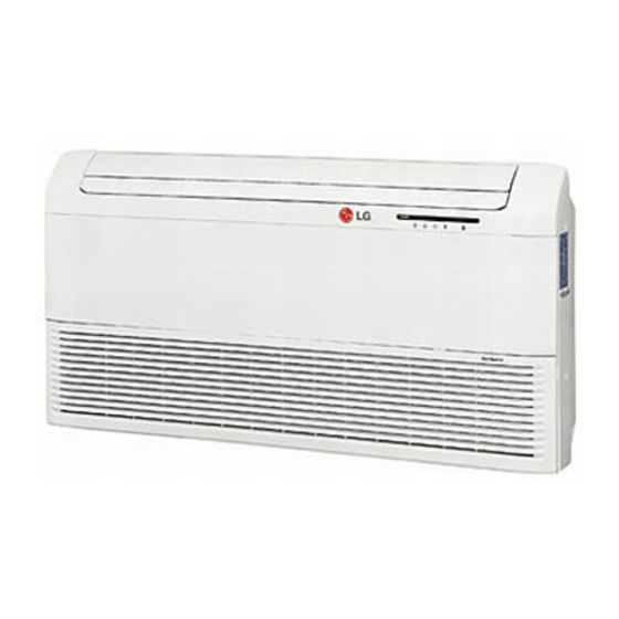
Air Conditioner
INSTALLATION MANUAL
Type : Convertible
IMPORTANT
• Please read this instruction manual completely
before installing the product.
• Installation work must be performed in
accordance with the national wiring standards
by authorized personnel only.
• Please retain this installation manual for future
reference after reading it thoroughly.
LG
Advertisement
Table of Contents


Need help?
Do you have a question about the LVNH246BLA1 and is the answer not in the manual?
Questions and answers