Advertisement
Quick Links
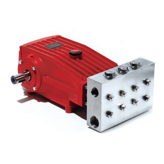
Model
LP301A-0081
Contents:
Installation Instructions:
Specifications:
Exploded View:
Parts List/Repair Kits:
Repair Instructions:
Torque Specifications:
Pump Mounting Selection Guide:
Trouble Shooting/Preventative
Maintenance Check-List
& Recommended Spare Parts List:
Dimensions:
Warranty Information:
Triplex Ceramic
Plunger Pump
Operating Instructions/
Manual
Teflon/Nitrile Seals with
Viton O-Rings
page 2
page 3
page 4
page 5
page 6-9
page 9
page 9
page 10
page 11
back page
Advertisement

Related Manuals for Giant LP301A-0081


Summary of Contents for Giant LP301A-0081
- Page 1 Model Triplex Ceramic Plunger Pump LP301A-0081 Operating Instructions/ Manual Teflon/Nitrile Seals with Viton O-Rings Contents: Installation Instructions: page 2 Specifications: page 3 Exploded View: page 4 Parts List/Repair Kits: page 5 Repair Instructions: page 6-9 Torque Specifications: page 9 Pump Mounting Selection Guide:...
-
Page 2: Installation Instructions
Crankcase oil should be changed after the first 50 hours of operation, then at regu- 4. Run the pump dry approximately 10 seconds lar intervals of 500 hours or less depending to drain the water before exposure to freezing on operating conditions. temperatures. NOTE: Contact Giant Industries for Service School Information. Phone: (419)-531-4600... - Page 3 HORSEPOWER INFORMATION We recommend that a 1.15 service factor be specified when selecting an electric motor as the power source. To compute specific pump horsepower requirements, use the following formula: HP = (GPM X PSI) / 1450 LP301A-0081 PULLEY SELECTION AND HORSEPOWER REQUIREMENTS RPM GPM 2500 PSI 3000 PSI 3500 PSI 4000 PSI 12.2...
- Page 4 Exploded View - LP301A-0081 Important! The stainless steel valve plugs (48) can seize when being screwed out of the cas- ing. To release tension beforehand, strike the plugs 1-2 times with a steel hammer on the top before screwing them out. Coat threads with antiseize (e.g. Fel-Pro Nickel Anti-Seize 51119)
-
Page 5: Repair Kits
Spare Parts List - LP301A-0081 ITEM PART DESCRIPTION ITEM PART DESCRIPTION 13238 Leakage Seal 07759 Crankcase 13240 Seal Case 13000 Oil Filler Plug Assy. 05940 Cover Plate 07140 O-Ring, Seal Case 38A 13241 Support Ring for 38 07223-0100 Spring Ring 12055-0001 O-Ring 05051 Hexagon Screw 39A 07693 Support Ring for 39 06085 Crankcase Cover 07104 O-ring, Crankcase Cover... - Page 6 REPAIR INSTRUCTIONS - LP301A-0081 NOTE: Always take time to lubricate all metal and non-metal parts with a light film of oil before reassembling. This step will help ensure proper fit, at the same time protecting the pump non-metal parts (elastomers) from cutting and scoring. TO CHECK VALVES 1) Loosen and remove 2) Remove the support ring 3) Take out discharge valve (44B), O-ring (44A) and assemblies (46) by pulling tension plugs (48) with a them upwards out of the tension spring (45).
- Page 7 REPAIR INSTRUCTIONS - LP301A-0081 NOTE: Always take time to lubricate all metal and non-metal parts with a light film of oil before reassembling. This step will help ensure proper fit, at the same time protecting the pump non-metal parts (elastomers) from cutting and scoring. TO CHECK SEALS AND PLUNGER PIPE 6) Loosen the 8 nuts (49A) Remove the seal sleeve 8) Remove seal case (37) with a 19mm socket and (35) from the manifold from seal sleeve (35).
- Page 8 REPAIR INSTRUCTIONS - LP301A-0081 Weep Hole 12) Check plunger surface (29B). If plunger pipe is worn out, 13) Replace complete seal loosen tension screws (29C) with a 15mm socket and sleeve (35)/seal case (37) pull off plunger pipe to the front. Clean front surface of assembly into crankcase plunger (29B) thoroughly.
-
Page 9: Pump Mounting Selection Guide
REPAIR INSTRUCTIONS - LP301A-0081 TO DISMANTLE GEAR END After removing valve casing (43) and plunger pipe (29B), drain the oil. Remove the gear cover (4) and both bearing covers (14). Loosen connecting rod screws (24A) and push the front of the connecting rod (24) forward as far as possible into the crosshead guide. IMPORTANT! Connecting rods (24) are marked for identification. Do not twist connecting rod halves. Con- necting rod is to be reinstalled in the same position on shaft journals. Turning the crankshaft (22) slightly, hit it out carefully to the side with a rubber hammer. - Page 10 Excessive vacuum Reduce suction vacuum Cracked plungers Replace plungers Inlet pressure too high Reduce inlet pressure High Crankcase Wrong Grade of oil Giant oil is recommended Temperature Improper amount of oil in crankcase Adjust oil level to proper amount Preventative Maintenance Check List & Recommended Spare Parts List Every Check Daily...
- Page 11 Dimensions Inches (mm) - LP301A-0081...
- Page 12 Giant Industries which are deemed to be defective due to work- manship or failure of material. A Returned Goods Authorization (R.G.A.) number and completed warranty evaluation form is required prior to the return to Giant Industries of all products under war- ranty consideration. Call (419)-531-4600 or fax (419)-531-6836 to obtain an R.G.A. number.
Need help?
Do you have a question about the LP301A-0081 and is the answer not in the manual?
Questions and answers