Giant Triplex Ceramic Plunger Pump LP350 Operating Instructions & Service Manual
Triplex ceramic plunger pump operating instructions/ repair and service manual
Hide thumbs
Also See for Triplex Ceramic Plunger Pump LP350:
Advertisement
Quick Links
Models
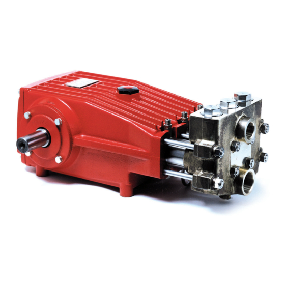
LP350, LP400, LP450
Updated 2/02
Triplex Ceramic
Plunger Pump
Operating Instructions/
Repair and Service
Manual
Contents:
Installation Instructions:
Pump Specifications:
Exploded View:
Parts List/Kits/Torque Specs:
Trouble Shooting Chart:
Spare Parts List:
Repair Instructions:
Dimensions:
Warranty Information:
page 2
pages 3-5
page 6
page 7
page 8
page 8
page 9-11
back page
back page
Advertisement

Related Manuals for Giant Triplex Ceramic Plunger Pump LP350


Summary of Contents for Giant Triplex Ceramic Plunger Pump LP350
- Page 1 Models LP350, LP400, LP450 Updated 2/02 Plunger Pump Operating Instructions/ Repair and Service Manual Contents: Installation Instructions: Pump Specifications: Exploded View: Parts List/Kits/Torque Specs: Trouble Shooting Chart: Spare Parts List: Repair Instructions: Dimensions: Warranty Information: page 2 pages 3-5 page 6 page 7 page 8 page 8...
-
Page 2: Installation Instructions
INSTALLATION INSTRUCTIONS Installation of the Giant Industries, Inc., pump is not a complicated procedure, but there are some basic steps common to all pumps. The following information is to be considered as a general outline for installa- tion. If you have unique requirements, please contact Giant Industries, Inc. - Page 3 750 16.9 11.8 805 18.2 12.6 865 19.5 13.6 940 21.2 14.7 1000 22.6 15.7 F @1000 RPM F Up to 500 RPM HP = (GPM x PSI) / 1440 15.7 18.0 20.1 23.1 23.5 27.1 25.3 29.0 27.1 31.2 29.5 33.9...
- Page 4 21.0 865 13.0 18.1 22.6 940 14.2 19.7 24.6 1000 15.1 20.9 26.1 F @1000 RPM F Up to 500 RPM HP = (GPM x PSI) / 1440 15.7 18.8 20.1 24.1 23.5 28.2 25.3 30.3 27.1 32.6 29.5 35.4 31.4...
- Page 5 16.5 865 17.0 11.8 17.7 940 18.5 12.8 19.3 1000 19.7 13.7 20.5 F @1000 RPM F Up to 500 RPM HP = (GPM x PSI) / 1440 13.7 17.8 17.5 22.7 20.5 26.7 22.0 28.6 23.6 30.7 25.7 33.4 27.3...
- Page 6 LP350, LP400, LP450 - EXPLODED VIEW...
- Page 7 LP350, LP400 & LP450 PARTS LIST ITEM # PART # DESCRIPTION 07759 Crankcase 13000 Oil filler plug assy. 06085 Crankcase Cover 07104 O-ring, Crankcase cover 07186 Oil Sightglass with Gasket 06086 Oil Dipstick 01009 O-Ring, Dipstick 01010 Cylinder Screw 01011 Spring Ring 07109 Plug...
- Page 8 PUMP SYSTEM MALFUNCTION MALFUNCTION CAUSE The Pressure and/ Worn packing seals or the Delivery Broken valve spring Drops Belt slippage Worn or Damaged nozzle Fouled discharge valve Fouled inlet strainer Worn or Damaged hose Worn or Plugged relief valve on pump Cavitation pump for restrictions Unloader...
- Page 9 REPAIR INSTRUCTION - LP350, LP400, LP450 TO CHECK VALVES 1) With a 30mm wrench remove the three (3) tension plugs (48) from top of valve casing (43). 4) Inspect valve seats (46A) and valve plates (46B) for damage and replace if needed. Check valve casing (43) surfaces for damage.
- Page 10 REPAIR INSTRUCTION - LP350, LP400, LP450 9) Remove seal case (37) from seal sleeve (35). 40 (2) 12) Remove v-sleeves (40) and support ring (41) for seal case (37) and replace with new elastomers. Lubricate parts before reinstalling into seal sleeve. Replace seal sleeve/seal case assembly (35/37) into the valve casing (43).
-
Page 11: Disassembly Of Crankcase
REPAIR INSTRUCTIONS - LP350, LP400, LP450 DISASSEMBLY OF CRANKCASE 1) Remove valve casing (43) and plunger pipe (29B), drain oil. 2) Screw off gear cover (4) and bearing cover (14). 3) Remove connecting rod screws (24) and push the front of connecting rod forward as far as possible. Remove back halves of connecting rods, note which position from which they came from. - Page 12 LP350, LP400 & LP450 DIMENSIONS GIANT INDUSTRIES LIMITED WARRANTY Giant Industries, Inc. pumps and accessories are warranted by the manufacturer to be free from defects in workmanship and material as follows: For portable pressure washers and car wash applications, the discharge manifolds will never fail, period.
Need help?
Do you have a question about the Triplex Ceramic Plunger Pump LP350 and is the answer not in the manual?
Questions and answers