Table of Contents
Advertisement
Quick Links
Advertisement
Table of Contents

Related Manuals for Newland EM50S-10


Summary of Contents for Newland EM50S-10
- Page 1 SCANNING MADE SIMPLE EM50S-10 / EM50S-20 OEM scan engine integration guide...
- Page 2 All pictures in this manual are for reference only and actual product may differ. Regarding to the product modification and update, Fujian Newland Auto-ID Tech. Co., Ltd. reserves the right to make changes to any software or hardware to improve reliability, function, or design at any time without notice.
-
Page 3: Revision History
Revision History Version Description Date V1.0.0 Initial release. April 16, 2019 V1.0.1 Updated the Operating Voltage / Current section. May 17, 2019 Updated the maximum operating current and idle current in the table 3-1. V1.0.2 Updated the description of the note in the Operating Voltage/Current October 30, 2019 section. -
Page 5: Table Of Contents
Thermal Considerations ............................6 External Optical Elements ............................6 Installation Orientation ............................. 7 Mounting ................................... 7 Mechanical Mounting Dimensions for EM50S-10 (Unit: mm) ................... 8 Mechanical Mounting Dimensions for EM50S-20 (Unit: mm) ................... 9 Housing Design ................................12 Optics ..................................... 12 Window Placement .............................. - Page 6 Eye Safety ................................18 Chapter 3 Electrical Specifications ............................19 Power Supply ................................. 19 Ripple Noise ................................... 19 DC Characteristics ................................. 19 Operating Voltage / Current ........................... 19 I/O Voltage ................................20 Timing Sequence ................................20 Power Up and Power Down Timing Sequence ...................... 20 Chapter 4 Interfaces ...................................
-
Page 7: About This Guide
Newland’s SDK. ※ Note: This guide provides general instructions for the installation of the engine into a customer's device. Fujian Newland Auto-ID Tech. Co., Ltd. recommends an opto-mechanical engineer should conduct an opto-mechanical analysis before integration. -
Page 8: Related Documents
Related Documents • 12-pin connector specification, HIROSE Corporation, Model: FH34SRJ-12S-0.5SH(50), https://www.hirose.com/cn/... -
Page 9: Chapter 1 Getting Started
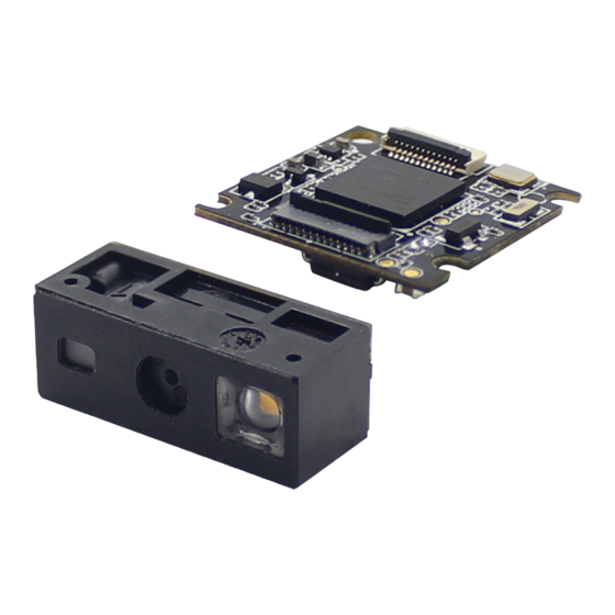
Chapter 1 Getting Started Introduction The EM50S is an area image engine for barcode reading. It includes a laser aiming system, an LED illumination system and a 12-pin FPC connector. LED Compliance Statement The EM50S complies with IEC 62471:2006 for LED safety. Laser Compliance Statement The EM50S is certified to be in compliance with IEC 60825-1:2014 as a class 1 laser product. -
Page 10: Illumination
Figure 1-1 System Block Diagram Illumination Aimer 12-pin Connector CMOS The 12-pin FPC connector on the engine can be connected to a host device with an FFC cable. For information about this cable, please see the “12-pin FFC Cable” section in Chapter 4. Illumination The EM50S has a white LED for supplementary lighting, making it possible to scan barcodes even in complete darkness. -
Page 11: Chapter 2 Installation
Chapter 2 Installation Introduction This chapter explains how to install the EM50S, including general requirements, housing design, and physical and optical information. △ Caution: Do not touch the imaging lens when installing the engine. Be careful not to leave fingerprints on the lens. !... -
Page 12: Ambient Environment
CPU, CIS, LEDs, DC/DC, etc and could result in a 40° C (EM50S-10) /35° C (EM50S-20) increase inside the engine. Overheating can degrade image quality and affect scanning performance. Given that, the following precautions should be taken into consideration when integrating the EM50S. -
Page 13: Installation Orientation
The EM50S series include two models -- EM50S-10 and EM50S-20 -- to cater for different mounting needs. For the EM50S-10 (the decoder board and the imager already assembled as one), the user can just mount the assembled unit on the target device. -
Page 14: Mechanical Mounting Dimensions For Em50S-10 (Unit: Mm)
Mechanical Mounting Dimensions for EM50S-10 (Unit: mm) Figure 2-2... -
Page 15: Mechanical Mounting Dimensions For Em50S-20 (Unit: Mm)
Mechanical Mounting Dimensions for EM50S-20 (Unit: mm) Imager Figure 2-3... - Page 16 Decoder Board Figure 2-4...
- Page 17 FPC Cable 50.0 Figure 2-5 Installation of FPC Cable EM50S-10: Figure 2-6...
-
Page 18: Housing Design
EM50S-20: Figure 2-7 Housing Design ※ Note: Conduct an optical analysis for the housing design to ensure optimal scanning and imaging performance. Housing design should make sure that internal reflections from the aiming and illumination system are not directed back to the engine. -
Page 19: Window Placement
Window Placement The window should be positioned properly to let the illumination and aiming beams pass through as much as possible and no reflections back into the engine (reflections can degrade the reading performance of the engine). There are two window placement options. •... -
Page 20: Window Material And Color
Window Material and Color Window material must be clear. Use only cell-cast plastics or optical glass. PMMA, ADC and chemically tempered glass are recommended. Window material selected for the engine should meet or exceed the specifications specified in Table 2-4. •... -
Page 21: Window Size
The AR coating specifications below should be met when using an AR coated window. Single side AR coating: 92% minimum transmittance within spectrum range from 420 nm to 730 nm. Double side AR coating: 97% minimum transmittance within spectrum range from 420 nm to 730 nm. Window Size The window must not block the field of view and should be sized to accommodate the aiming and illumination envelopes shown below. -
Page 22: Em50S-10
EM50S-10 Horizontal: Vertical: Figure 2-9... -
Page 23: Em50S-20
EM50S-20 Horizontal: Vertical: Figure 2-10... -
Page 24: Roll, Skew And Pitch
Three different reading angles, roll, skew and pitch are illustrated in Figure 2-10 Roll refers to rotation around the Z axis, skew to rotation around the X axis and pitch to rotation around the Y axis. For the engine’s technical specifications, please visit the Newland website or contact your dealer. Figure 2-11 Ambient Light The EM50S shows better performance with ambient light. -
Page 25: Chapter 3 Electrical Specifications
Chapter 3 Electrical Specifications Power Supply Do not power up the EM50S until it is properly connected. Be sure the power is cut off before connecting a cable to or disconnecting a cable from the host interface connector. Hot-plugging could damage the engine. Unstable power supply or sharp voltage drops or unreasonably short interval between power-ons may lead to unstable performance of the engine. -
Page 26: I/O Voltage
I/O Voltage Table 3-2 VDD=3.3 V, VSS=0 V, T=23° C Parameter Minimum Maximum Unit Timing Sequence Power Up and Power Down Timing Sequence Figure 3-1 1. In the diagram above, it takes A+B (less than 1s) for the engine to power up: A is reset time (about 560ms), B is time needed to start the engine (including bootloader execution, kernel boot and decoding chip initialization). -
Page 27: Chapter 4 Interfaces
Chapter 4 Interfaces Interface Pinouts The host interface connector of the EM50S is a 12-pin FPC connector, which can be used as TTL-232 interface or USB interface. The figure below illustrates the position of 12-pin FPC connector on the EM50S’s decoder board, as well as the pin 1 location. -
Page 28: 12-Pin Fpc Connector
12-pin FPC Connector The following table lists the pin functions of the 12-pin FPC connector. Table 4-1 PIN# Signal Function Remark PIN1 No connection 3.3V power supply input Power-supply ground TTL level 232 receive data TTL level 232 transmit data USB_D- USB D- differential data signal USB_D+... - Page 29 ※ 3 This output signal can be used by an external LED to indicate good read status. The LED pin (PIN 10) produces a low output (default duration: 20ms, user-programmable) when a good read occurs. The Good Read LED can be programmed On or Off. To learn how to program these parameters, please see the EM50S user guide.
-
Page 30: Connector/Cable Specifications (Unit: Mm)
Connector/Cable Specifications (Unit: mm) The EM50S is equipped with a 12-pin FPC connector. 12-pin FPC Connector The 12-pin FPC connector on the EM50S is supplied by Hirose Electric Co., Ltd. Model No.: FH34SRJ-12S-0.5SH(50), dual contact. Figure 4-2... -
Page 31: 12-Pin Ffc Cable
12-pin FFC Cable A 12-pin cable can be used to connect the engine’s 12-pin FPC connector to a host device. Figure 4-3... -
Page 32: External Circuit Design
External Circuit Design Good Read LED Circuit The circuit below can be used to drive an external LED for indicating good read. The LED signal is from PIN 10 of the 12-pin FPC connector. Figure 4-4 Beeper Circuit The circuit below can be used to drive an external beeper. The BUZ signal is from PIN 9 of the 12-pin FPC connector. Figure 4-5... -
Page 33: Trigger Circuit
Trigger Circuit The circuit below can be used to provide the engine with a signal to trigger a scan and decode session. The nTRIG signal is from PIN 12 of the 12-pin FPC connector. Figure 4-6 External Illumination LED Circuit The circuit below can be used to control external illumination LED when the user wants to add external illumination to further improve lighting. -
Page 34: Reset Circuit
Reset Circuit The circuit below can be used to reset the engine by giving a 200μs low pulse on the nRESET pin (PIN 11) on the host interface. The host device can send the RESET signal through GPIO. Figure 4-8... -
Page 35: Chapter 5 Auxiliary Tools
The EM50S can be connected to the EVK via a 12-pin FFC cable type 1 (contacts on the same side). Either USB connection or RS-232 connection can be used when connecting the EVK to a host device. EasySet EasySet is a Windows-based configuration tool developed by Newland, which can be used to configure the EM50S. - Page 36 SCANNING MADE SIMPLE Need more info? Contact us or one of Newland EMEA HQ our partners at newland-id.com/partners +31 (0) 345 87 00 33 info@newland-id.com newland-id.com...
Need help?
Do you have a question about the EM50S-10 and is the answer not in the manual?
Questions and answers