Table of Contents
Advertisement
Quick Links
Advertisement
Table of Contents

Related Manuals for Newland EM2037-V4


Summary of Contents for Newland EM2037-V4
- Page 1 SCANNING MADE SIMPLE EM2037-V4 OEM scan engine integration guide...
- Page 2 All pictures in this manual are for reference only and actual product may differ. Regarding to the product modification and update, Fujian Newland Auto-ID Tech. Co., Ltd. reserves the right to make changes to any software or hardware to improve reliability, function, or design at any time without notice.
-
Page 3: Revision History
Revision History Version Description Date V1.0.0 Initial release. September 6, 2018 1. Updated the “Roll, Skew and Pitch” section in Chapter 1. Updated Table 4-1 and added the “Power On LED Circuit” section in V1.0.1 September 20, 2018 Chapter 4. -
Page 5: Table Of Contents
Table of Contents Revision History ..................................- 3 - About This Guide..................................1 Introduction ..................................1 Chapter Description ................................1 Explanation of Symbols ..............................1 Related Documents ................................2 Chapter 1 Getting Started ................................3 Introduction ..................................3 Illumination ..................................4 Aimer .................................... - Page 6 Power Supply ................................. 17 Ripple Noise ................................... 17 DC Characteristics ................................. 17 Operating Voltage / Current ........................... 17 I/O Voltage ................................18 Timing Sequence ................................18 Power Up and Power Down Timing Sequence ...................... 18 Chapter 4 Interfaces ................................... 19 Interface Pinouts ................................
-
Page 7: About This Guide
Newland’s SDK. ※ Note: This guide provides general instructions for the installation of the engine into a customer's device. Fujian Newland Auto-ID Tech. Co., Ltd. recommends an opto-mechanical engineer should conduct an opto-mechanical analysis before integration. -
Page 8: Related Documents
Related Documents • 12-pin connector specification, CviLux Corporation, Model: CF20121V0R0-LF, https://cvilux.en.taiwantrade.com/ • 5-pin box connector specification, Xiamen Lianye Electronics Co., Ltd., Model: PH-5AW, http://www.lyconnxm.com/... -
Page 9: Chapter 1 Getting Started
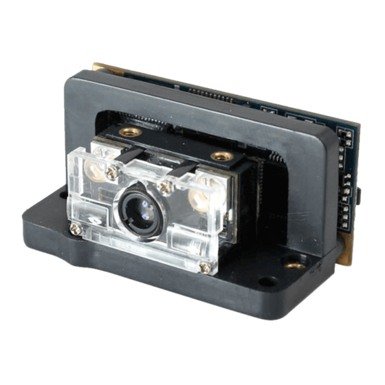
Chapter 1 Getting Started Introduction The EM2037 is an area image engine for barcode reading. It includes an LED aiming system, and an LED illumination system. LED Compliance Statement The EM2037 complies with IEC 62471:2006 for LED safety. The EM2037 contains: •... -
Page 10: Illumination
Illumination The EM2037 has two red LEDs (wavelength: 612nm-624nm) for supplementary lighting, making it possible to scan barcodes even in complete darkness. The illumination can be turned On or Off. The EM2037 uses red LEDs for illumination, so the engine shows better reading performance on barcodes printed in non-red colors. For applications involving red barcodes, it is advised to turn off the engine’s illumination and use non-red supplementary lighting (such as green) instead. -
Page 11: Chapter 2 Installation
Chapter 2 Installation Introduction This chapter explains how to install the EM2037, including general requirements, housing design, and physical and optical information. △ Caution: Do not touch the imaging lens when installing the engine. Be careful not to leave fingerprints on the lens. !... -
Page 12: Thermal Considerations
Thermal Considerations Electronic components in the EM2037 will generate heat during the course of their operation. Operating the EM2037 in continuous mode for an extended period may cause temperatures to rise on CPU, CIS, LEDs, DC/DC, etc. Overheating can degrade image quality and affect scanning performance. Given that, the following precautions should be taken into consideration when integrating the EM2037. -
Page 13: Mechanical Mounting Dimensions For The All-In-One Type (Unit: Mm)
Mechanical Mounting Dimensions for the All-in-one Type (Unit: mm) Front View Figure 2-2 Bottom View Figure 2-3... -
Page 14: Mechanical Mounting Dimensions For The Imager (Unit: Mm)
Side View Figure 2-4 Mechanical Mounting Dimensions for the Imager (Unit: mm) Front View Figure 2-5... - Page 15 Top View Figure 2-6 Bottom View Figure 2-7 Side View Figure 2-8...
-
Page 16: Mechanical Mounting Dimensions For The Decoder Board (Unit: Mm)
Mechanical Mounting Dimensions for the Decoder Board (Unit: mm) Figure 2-9 Figure 2-10 (With 5-pin box connector) Figure 2-11 (Without 5-pin box connector) -
Page 17: Housing Design
Housing Design ※ Note: Conduct an optical analysis for the housing design to ensure optimal scanning and imaging performance. Housing design should make sure that internal reflections from the aiming and illumination system are not directed back to the engine. The reflections from the housing or window can cause problems. For particular window tilt angles, the unwanted reflections can bounce off the top or bottom and reach the engine. -
Page 18: Window Material And Color
Table 2-2 Distance from the front of the engine housing (b) Minimum Angle (Tilted Window) 10mm 15mm 20mm Uncoated, minimum window positive tilt (+w) 25° 20° 18° 16° Uncoated, minimum window negative tilt (-w) Anti-reflection coated, single side, minimum window positive tilt (+w) 22°... -
Page 19: Coatings And Scratch Resistance
Pay extra attention to the wavefront distortion when using plastic materials. Plastic materials are not recommended for tilted windows; colored windows are not recommended if the engine is used to scan barcodes on moving objects. Coatings and Scratch Resistance Scratch on the window can greatly reduce the performance of the EM2037. It is suggested to use abrasion resistant window material or coating. - Page 20 • SR version Horizontal: Vertical: Figure 2-13...
- Page 21 • HD version Horizontal: Vertical: Figure 2-14...
-
Page 22: Roll, Skew And Pitch
Three different reading angles, roll, skew and pitch are illustrated in Figure 2-15. Roll refers to rotation around the Z axis, skew to rotation around the X axis and pitch to rotation around the Y axis. For the engine’s technical specifications, please visit the Newland website or contact your dealer. Figure 2-15 Ambient Light The EM2037 shows better performance with ambient light. -
Page 23: Chapter 3 Electrical Specifications
Chapter 3 Electrical Specifications Power Supply Do not power up the EM2037 until it is properly connected. Be sure the power is cut off before connecting a cable to or disconnecting a cable from the host interface connector. Hot-plugging could damage the engine. Unstable power supply or sharp voltage drops or unreasonably short interval between power-ons may lead to unstable performance of the engine. -
Page 24: I/O Voltage
I/O Voltage Table 3-2 VDD=3.3 V, VSS=0 V, T=23° C Parameter Minimum Maximum Unit -0.3 Timing Sequence Power Up and Power Down Timing Sequence Figure 3-1 1. In the diagram above, it takes A+B (about 970ms) for the engine to power up: A is reset time (about 298ms), B is time needed to start the engine (including bootloader execution, kernel boot and decoding chip initialization). -
Page 25: Chapter 4 Interfaces
Chapter 4 Interfaces Interface Pinouts The physical interface of the EM2037 consists of 12-pin FPC connector and 5-pin box connector: • 12-pin FPC connector can be used as TTL-232 interface or USB interface. • 5-pin box connector can only be used as standard USB interface. The figure below illustrates the positions of 12-pin FPC connector and 5-pin box connector on the EM2037’s decoder board, as well as the pin layout of the FPC connector. -
Page 26: 12-Pin Fpc Connector
12-pin FPC Connector The following table lists the pin functions of the 12-pin FPC connector. Table 4-1 PIN# Signal Function Remark Not connected Power supply input Power-supply ground RXD/USB_D- TTL level 232 receive data/ USB D- differential data signal TTL level 232 transmit data nCTS/USB_D+ TTL level 232 clear to send /USB D+ differential data signal nRTS... -
Page 27: 5-Pin Box Connector
occurs. The Good Read LED can be programmed On or Off. To learn how to program these parameters, please see the EM2037 V4 user guide. For the external LED circuit design, please see the “Good Read LED Circuit” section in this chapter. If the nGoodRead pin is not used, leave it unconnected. -
Page 28: 5-Pin Box Connector
Figure 4-2 5-pin Box Connector The 5-pin box connector on the EM2037 is supplied by Xiamen Lianye Electronics Co., Ltd., Model No.: PH-5AW. Figure 4-3... -
Page 29: 12-Pin Ffc Cable
12-pin FFC Cable A 12-pin cable can be used to connect the engine’s 12-pin FPC connector to a host device. Figure 4-4... -
Page 30: 5-Pin Usb Female
5-pin USB Female A 5-pin USB female can be used to connect the engine’s 5-pin box connector (male) to a host device. Figure 4-5... -
Page 31: External Circuit Design
External Circuit Design Good Read LED Circuit The circuit below is used to drive an external LED for indicating good read. The left part shows internal LED driver circuit on the decoder board and the right part shows external circuit that users may utilize in actual application. The nGoodRead signal is from PIN 10 of the 12-pin FPC connector. -
Page 32: Trigger Circuit
Trigger Circuit The circuit below is used to provide the engine with a signal to trigger a scan and decode session. The right part shows internal trigger processing circuit on the decoder board and the left part shows external circuit that users may utilize in actual application. -
Page 33: Chapter 5 Auxiliary Tools
The EM2037 can be connected to the EVK via a 12-pin FFC cable type 1 (contacts on the same side). Either USB connection or RS-232 connection can be used when connecting the EVK to a host device. EasySet EasySet is a Windows-based configuration tool developed by Newland, which can be used to configure the EM2037. - Page 34 SCANNING MADE SIMPLE Need more info? Contact us or one of Newland EMEA HQ our partners at newland-id.com/partners +31 (0) 345 87 00 33 info@newland-id.com newland-id.com...
Need help?
Do you have a question about the EM2037-V4 and is the answer not in the manual?
Questions and answers